Manitowoc Published 08-06-19, Control # 237-09_v2 4-101
MLC165-1 OPERATOR MANUAL SETUP AND INSTALLATION
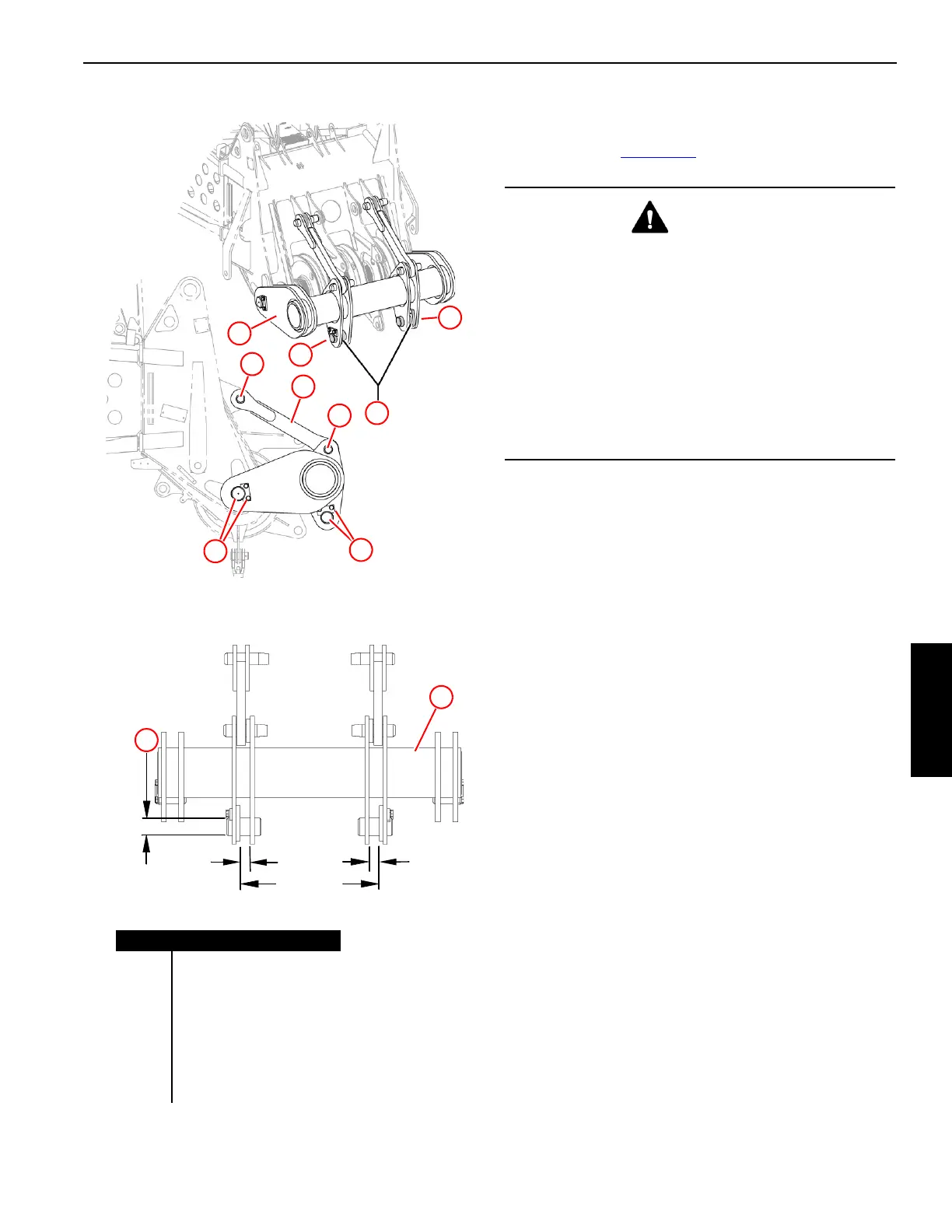
Install Pile Driver Adapter for Fixed Leads
If required, attach the optional pile driver adapter to the boom
point as shown in Figure 4-74
.
Operating Specifications
• Maximum Boom Length = 137.8 ft (42 m)
• Maximum Load Per Side = Design Load divided by 2
• Design Loads — “R”:
- 60,000 lb (2 7215,5 kg) at 65° Boom Angle
- 48,000 lb (2 1772,4) at 55° Boom Angle
Figure 4-74
1
2
3
2
5
4
Item Description
1 Adapter
2Pin
3Link
4 Pin with Keeper Plate
5 Pin with Keeper Plate
6 Connection Point
R Design Load
M100756
27.95 in
710 mm
2.09 in
53 mm
End View
All Linear Dimensions: ± 0.060 in (1,52 mm)
2.09 in
53 mm
Pin Hole
3.50 in
89 mm
81000908b
1
R
4
6
6
WARNING
Equipment Failure Hazard
The pile driver adapter shall be used only with freely
suspended loads.
Any side load or torque generated by the owner-supplied
attachments will reduce the design loads of the pile driver
adapter. In such cases, contact your Manitowoc dealer for
the specifications which meet your particular application.
The design loads given below apply to the pile driver
adapter only. In all cases, the pile driver adapter loads
must not exceed the capacities given in the applicable
Liftcrane Boom Capacities chart.
 Loading...


