SETUP AND INSTALLATION MLC165-1 OPERATOR MANUAL
4-114
Published 08-06-19, Control # 237-09_v2
Install the Wind Speed and Position Light
Components
If any wind speed or position light components have been
removed, re-install them now. They are stored in the job box.
If they are currently located on the boom top, relocate them
to the jib top (Figure 4-88
).
If any wind speed or position light components have been
removed, re-install them now.
Refer to the following drawings at the end of this section:
• Electric Accessory Assembly, Boom Top Indicator
• Electric Accessory Assembly, Wind Speed Indicator
NOTE To provide a good ground for the wind speed
indicator bracket, use star washers to attach the
bracket to the boom or jib top.
Connect the Jib Wiring
Refer to the ESI Boom Wiring drawing at the end of this
section.
1. Connect electric cables in the boom and jib to the proper
receptacles.
2. Connect CAN terminators to unused plugs. Failing to
perform this step will cause a fault alert and the
corresponding function will not operate properly.
3. To prevent dirt and moisture from entering electric
components, connect dust caps to all unused plugs,
CAN terminators, and receptacles.
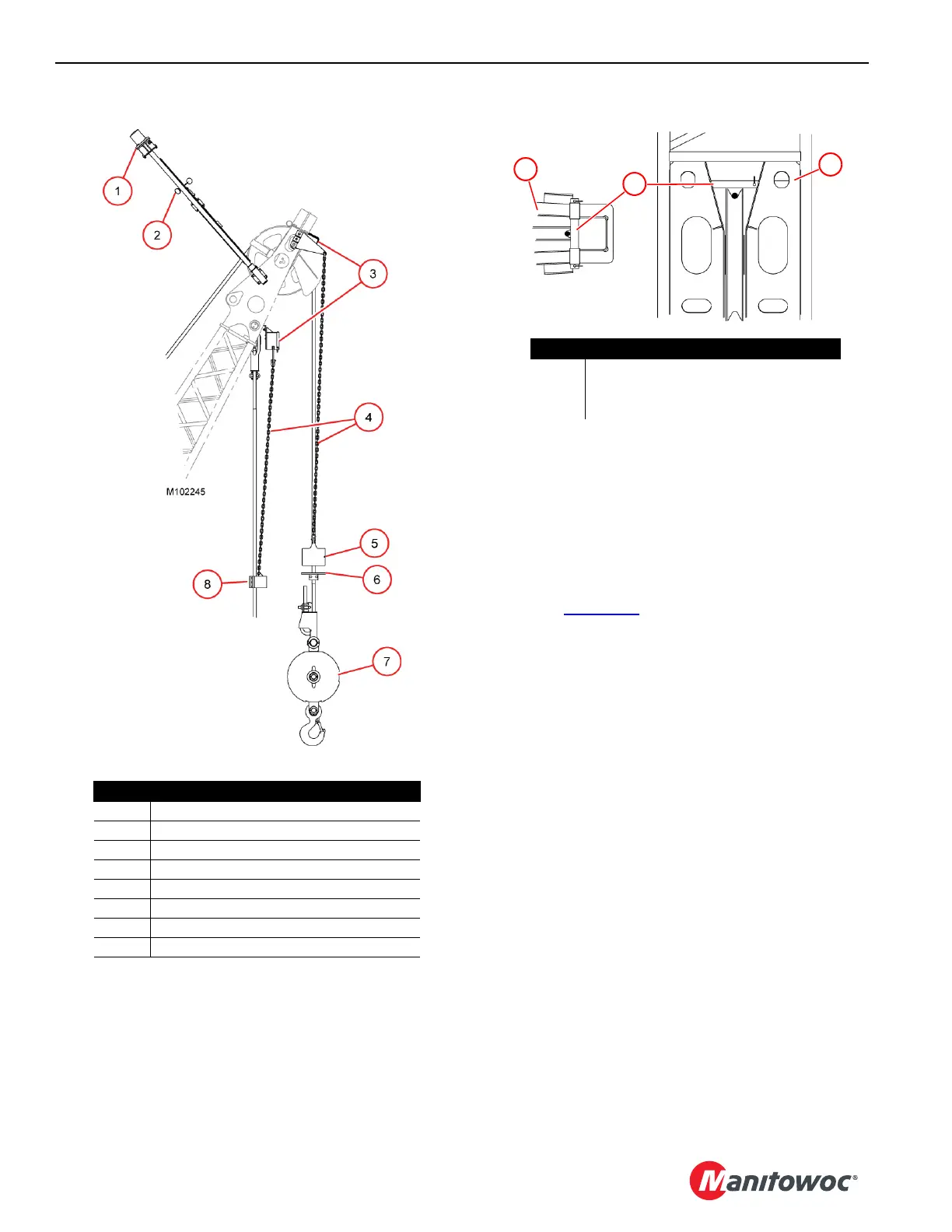
Figure 4-88
Item Description
1 Position Indicator Light
2 Wind Speed Indicator
3 Limit Switch (lower and upper boom point)
4Chain
5 Weight with 2-Chain Attachments
6Lift Plate
7 Hook and Weight Ball
8 Weight with 1-Chain Attachment
Item Description
1Jib Top
2Jib Strut
3 Rope Guard with Safety Pin(s)
Figure 4-89
3
1
2