Manitowoc Published 08-06-19, Control # 237-09_v2 4-121
MLC165-1 OPERATOR MANUAL SETUP AND INSTALLATION
Anchoring Wire Rope to Wedge Socket
See Figure 4-94 for the following procedure.
1. Assemble the wire rope and the wedge to the socket so
the live end of the wire rope is in a straight line with the
socket pin hole. Do not assemble WRONG as shown.
2. Allow the dead end of the wire rope to extend past the
end of the socket the amount shown.
3. Allow the wire rope to assume its natural lay.
4. Pull against the wedge and live end of the wire rope
enough to tighten the wedge in the socket.
5. Use a brass hammer to seat the wedge and wire rope as
deep into the socket as possible.
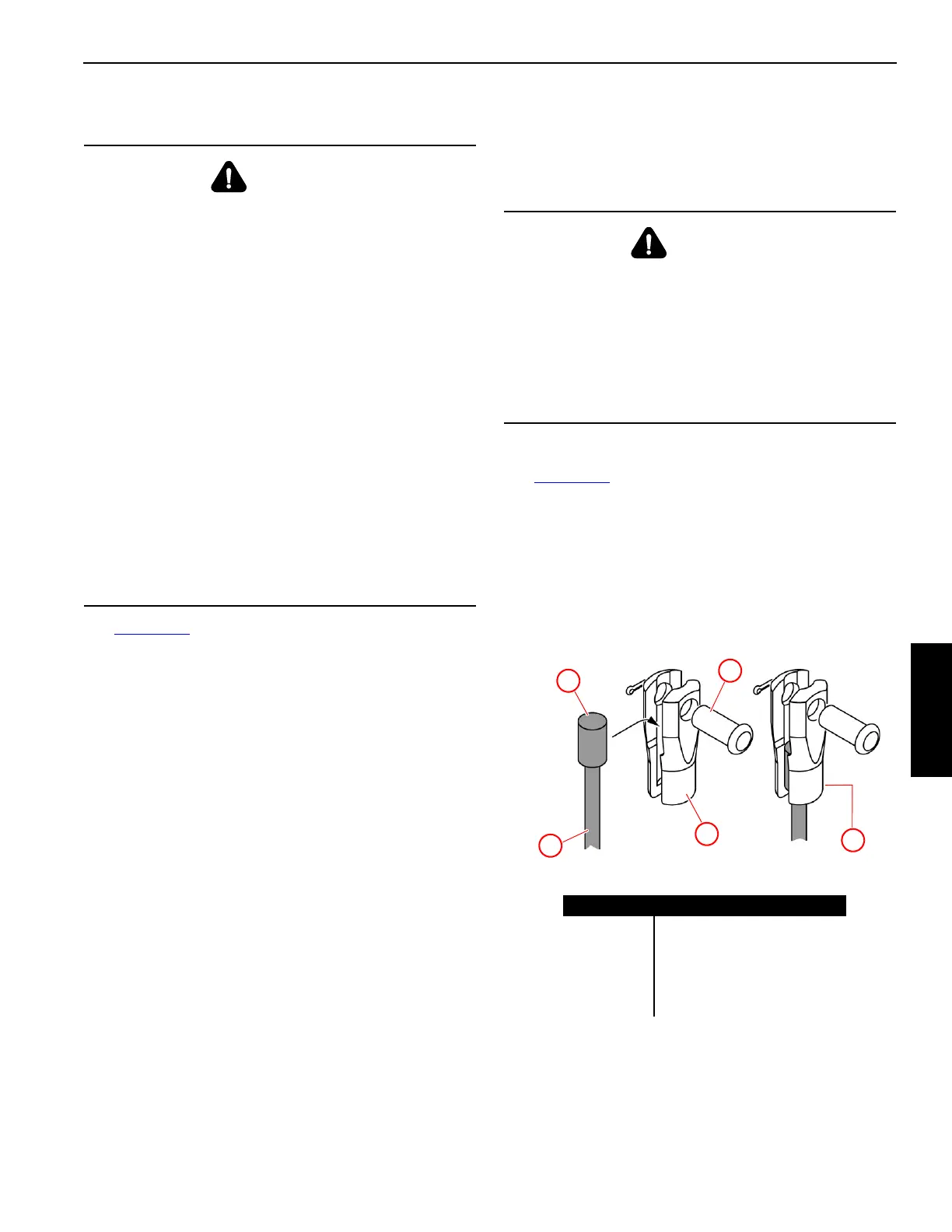
6. Attach a wire rope clip to the dead end of the wire rope
using one of the RIGHT methods shown. The rope clip
will aid in preventing the wire rope from being pulled out
of the socket.
NOTE Use Right Method A only if the wire rope clip is
small enough to be securely tightened to the dead
end. Right Method C is only for use with a
Terminator wedge socket.
7. After the socket is pinned in place, hoist the load slowly
so the wedge seats tightly. Do not shock load socket and
wedge.
Anchoring Wire Rope to Button Socket
See Figure 4-95 for the following procedure.
1. Remove the pin (4) from the button socket (3).
2. Install the button (2) end of load line (1) in the button
socket (3).
3. Pin the button socket (3) to the dead-end anchor point
(not shown).
4. If equipped, securely tighten the locking screw (5).
WARNING
Falling Load Hazard!
• Inspect all parts prior to use. Do not use parts that are
cracked or otherwise defective.
• Remove minor nicks, burrs, or rough edges from the
socket, wedge, or pin by lightly grinding. Do not
reduce the original dimensions by more than 10%.
• Do not reinstall shipping material (bolt, plastic strap or
wire) in the hole of the wedge or the socket after
assembling them. Discard these materials because
they can prevent the wedge from tightening in the
socket.
• Only use a wedge and socket that are the correct size
for the wire rope being used. Do not mix and match
parts from one assembly with parts from another
assembly.
• The Terminator™ socket and wedge has “go” and “no
go” holes to check for proper rope size.
• Attach the wire rope clip to the dead end of the wire
rope after assembling the wire rope to the wedge and
socket.
WARNING
Falling Load Hazard!
The wire rope can break if the following precaution is not
observed:
• Do not attach the dead end of the wire rope to the live
end of the wire rope with a wire rope clip. The wire
rope clip will transfer the load from the live side of
wire rope to the dead end, seriously weakening the
attachment.
M100459
Figure 4-95
(behind)
Item Description
1 Load Line
2 Button
3 Button Socket
4Pin
5 Locking Screw (if equipped)
1
2
3
4
5
 Loading...


