Electrical Specifications
AC Electrical Specifications
Copyright © 2008 Marvell Doc. No. MV-S104859-U0 Rev. E
December 2, 2008, Preliminary Document Classification: Proprietary Information Page 113
8.6.13 Secure Digital Input/Output (SDIO) Interface AC Timing
8.6.13.1 Secure Digital Input/Output (SDIO) AC Timing Table
Table 61: SDIO Host in High Speed Mode AC Timing Table
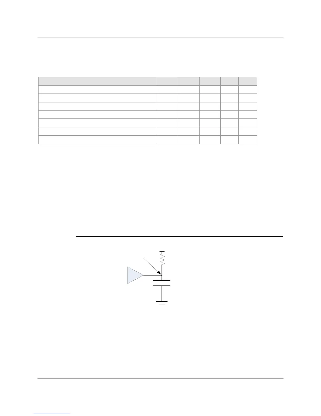
8.6.13.2 Secure Digital Input/Output (SDIO) Test Circuit
Figure 37: Secure Digital Input/Output (SDIO) Test Circuit
Description Symbol Min Max Units Notes
Clock frequency in Data Transfer Mode fCK 0 50 MHz -
Clock high/low level pulse w idth tWL/tWH 0.35 - tCK 1, 3
Clock rise/fall time tTLH/tTHL - 3.0 ns 1, 3
CMD, DAT output valid before CLK rising edge tDOVB 6.5 - ns 2, 3
CMD, DAT output valid after CLK rising edge tDOVA 2.5 - ns 2, 3
CMD, DAT input setup relative to CLK rising edge tISU 7.0 - ns 2
CMD, DAT input hold relative to CLK rising edge tIHD 0.0 - ns 2
Not e s :
General comment: tCK = 1/fCK.
1. Defined on VIL(max) and VIH(min) levels.
2. Defined on VDDIO/2 for Clock signal, and VIL(max) / VIH(min) for CMD & DAT signals.
3. For all signals, the load is CL = 10 pF.