System Power Up/Down and Reset Settings
Power-Up/Down Sequence Requirements
Copyright © 2008 Marvell Doc. No. MV-S104859-U0 Rev. E
December 2, 2008, Preliminary Document Classification: Proprietary Information Page 63
6 System Power Up/Down and Reset
Settings
This section provides information about the device power-up/down sequence and configuration at
reset.
6.1 Power-Up/Down Sequence Requirements
6.1.1 Power-Up Sequence Requirements
These guidelines must be applied to meet the 88F6281 device power-up requirements:
The non-core voltages (I/O and Analog) as listed in Table 31 must reach 70% of their voltage
level before the core voltages reach 70% of their voltage level.
The order of the power-up sequence between the non-core voltages is unimportant so long as
the non-core voltages power up before the core voltages reach 70% of their voltage level
(shown in Figure 2).
The order of the power-up sequence between the core voltages (VDD and VDD_CPU) is
unimportant.
The reset signal(s) must be asserted before the core voltages reach 70% of their voltage level
(shown in Figure 2).
The reference clock(s) inputs must toggle with their respective voltage levels before the core
voltages reach 70% of their voltage level (shown in Figure 2).
If VHV is set to burning mode (2.5V), which is a higher voltage than the VDD voltage, VDD must
be powered before VHV, to prevent the fuse from being accidentally burned.
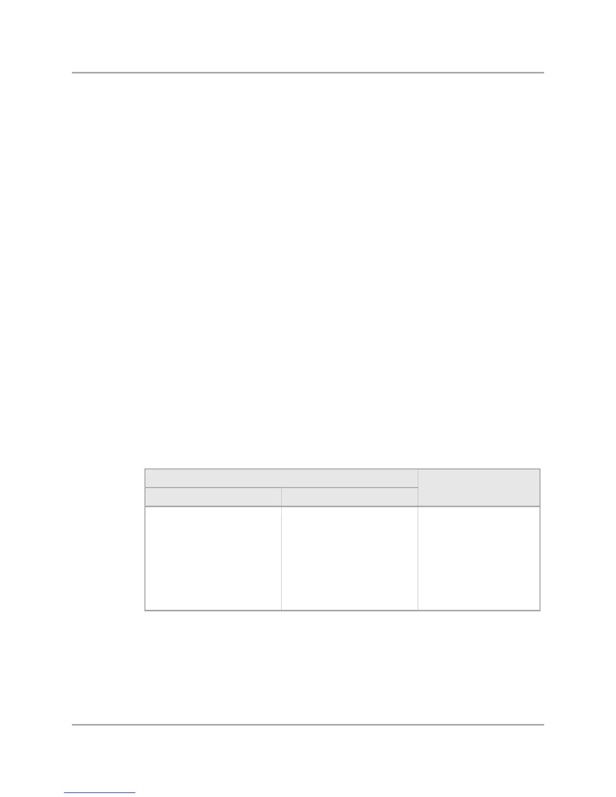
Table 31: I/O and Core Voltages
Non-Core Voltages Core Voltages
I/O Voltages Analog Power Supplies
VDD_GE_A
VDD_GE_B
VDD_M
VDDO
CPU_PLL_AVDD
CORE_PLL_AVDD
PEX_AVDD
RTC_AVDD
SATA0_AVDD
SATA1_AVDD
SSCG_AVDD
XTAL_AVDD
USB_AVDD
VDD
VDD_CPU