Electrical Specifications
AC Electrical Specifications
Copyright © 2008 Marvell Doc. No. MV-S104859-U0 Rev. E
December 2, 2008, Preliminary Document Classification: Proprietary Information Page 93
8.6.3 Reduced Gigabit Media Independent Interface (RGMII)
AC Timing
8.6.3.1 RGMII AC Timing Table
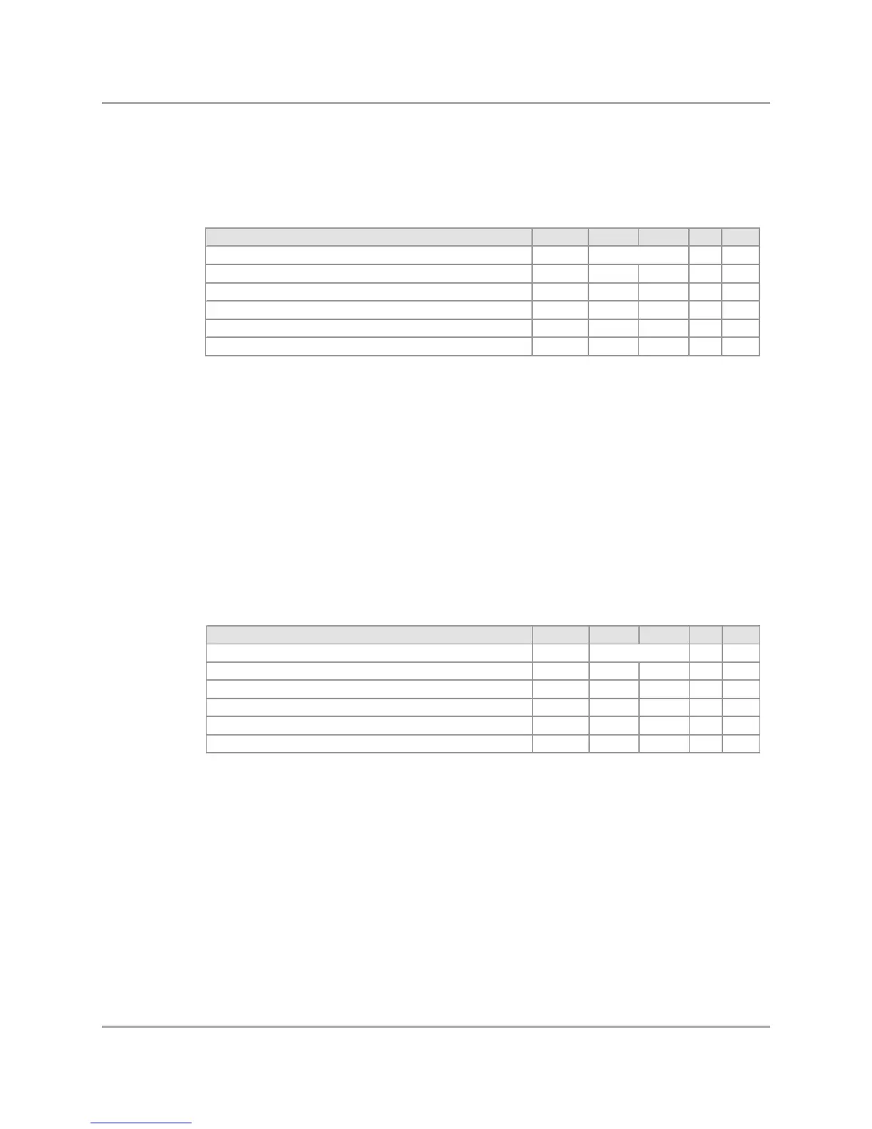
Table 49: RGMII 10/100/1000 AC Timing Table at 1.8V
Table 50: RGMII 10/100 AC Timing Table at 3.3V
Description Symbol Min Max Units Notes
Clock frequency fCK MHz -
Data to Clock output skew TskewT -0.50 0.50 ns 2
Data to Clock input skew TskewR 1.00 2.60 ns -
Clock cycle duration Tcyc 7.20 8.80 ns 1 , 2
Duty cycle for Gigabit Duty_G 0.45 0.55 tCK 2
Duty cycle for 10/100 Megabit Duty_T 0.40 0.60 tCK 2
Note s:
General comment: All values w ere measured from vddio/2 to vddio/2, unless otherw ise specified.
General comment: tCK = 1/fCK.
General comment: If the PHY does not support internal-delay mode, the PC board design requires
routing clocks so that an additional trace delay of greater than 1.5 ns and less
than 2.0 ns is added to the associated clock signal.
For 10/100 Mbps RGMII, the Max value is unspecified.
1. For RGMII at 10 Mbps and 100 Mbps, Tcyc will scale to 400 ns +/-40 ns and 40 ns +/-4 ns, respectively.
2. For all signals, the load is CL = 5 pF.
125.0
Description Symbol Min Max Units Notes
Clock frequency fCK MHz -
Data to Clock output skew Tskew T -0.50 0.50 ns 2
Data to Clock input skew TskewR 1.00 2.60 ns -
Clock cycle duration Tcyc 7.20 8.80 ns 1 , 2
Duty cycle for Gigabit Duty_G 0.45 0.55 tCK 2
Duty cycle for 10/100 Megabit Duty_T 0.40 0.60 tCK 2
Note s:
General comment: All values w ere measured from vddio/2 to vddio/2, unless otherw ise specified.
General comment: tCK = 1/fCK.
General comment: If the PHY does not support internal-delay mode, the PC board design requires
routing clocks so that an additional trace delay of greater than 1.5 ns
is added to the associated clock signal.
For 10/100 Mbps RGMII, the Max value is unspecified.
1. For RGMII at 10 Mbps and 100 Mbps, Tcyc will scale to 400 ns +/-40 ns and 40 ns +/-4 ns, respectively.
2. For all signals, the load is CL = 5 pF.
25.0