Electrical Specifications
AC Electrical Specifications
Copyright © 2008 Marvell Doc. No. MV-S104859-U0 Rev. E
December 2, 2008, Preliminary Document Classification: Proprietary Information Page 99
8.6.6 Serial Management Interface (SMI) AC Timing
8.6.6.1 SMI Master Mode AC Timing Table
Table 53: SMI Master Mode AC Timing Table
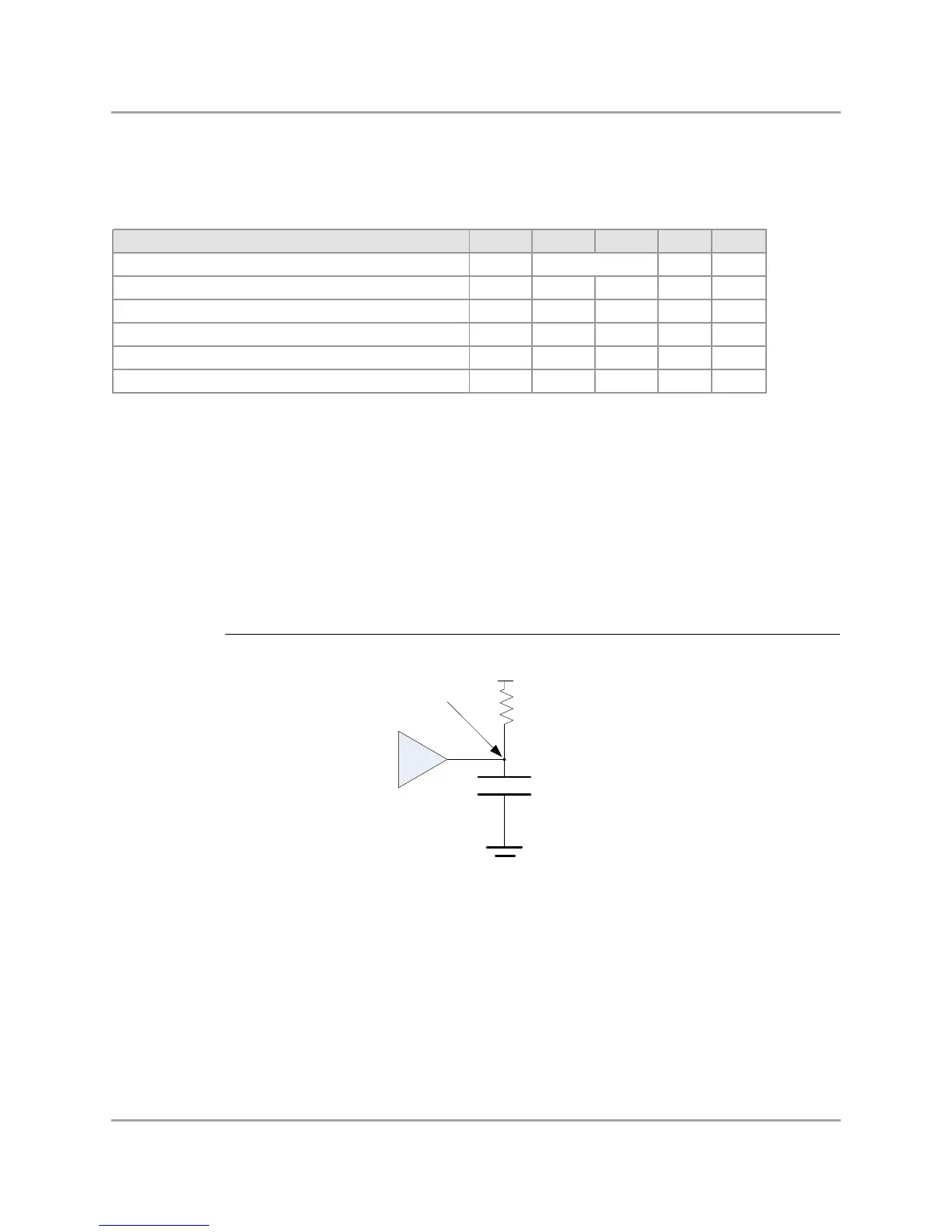
8.6.6.2 SMI Master Mode Test Circuit
Figure 17: MDIO Master Mode Test Circuit
Description Symbol Min Max Units Notes
MDC clock frequency fCK MHz 2
MDC clock duty cycle tDC 0.4 0.6 tCK -
MDIO input setup time relative to MDC rise time tSU 40.0 - ns -
MDIO input hold time relative to MDC rise time tHO 0.0 - ns -
MDIO output valid before MDC rise time tOVB 15.0 - ns 1
MDIO output valid after MDC rise time tOVA 15.0 - ns 1
Note s:
General comment: All timing values w ere measured from VIL(max) and VIH(min) levels, unless otherw ise specified.
General comment: tCK = 1/fCK.
1. For MDC signal, the load is CL = 390 pF, and for MDIO signal, the load is CL = 470 pF.
2. See "Reference Clocks" table for more details.
See note 2
CL
2 kilohm
VDDIO
Test Point
MDIO