Electrical Specifications
AC Electrical Specifications
Copyright © 2008 Marvell Doc. No. MV-S104859-U0 Rev. E
December 2, 2008, Preliminary Document Classification: Proprietary Information Page 95
8.6.4 Gigabit Media Independent Interface (GMII) AC Timing
8.6.4.1 GMII AC Timing Table
Table 51: GMII AC Timing Table
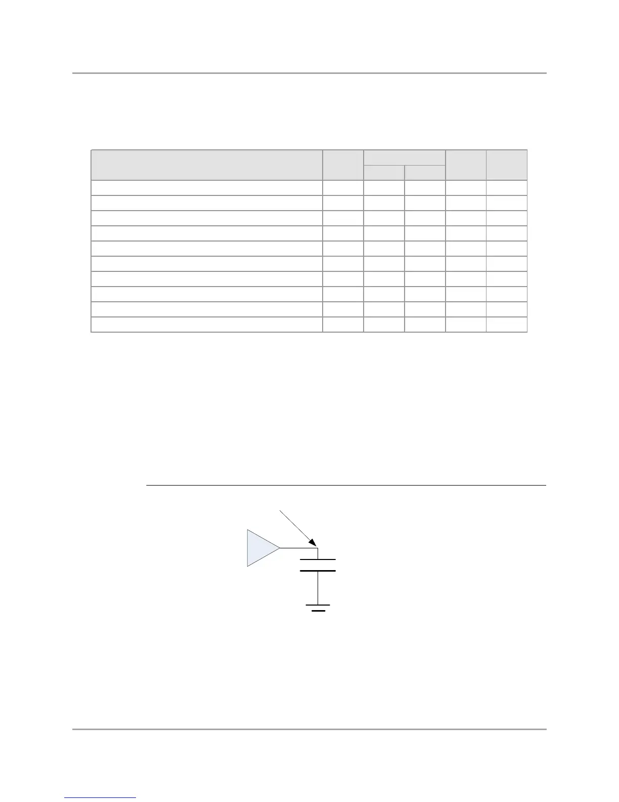
8.6.4.2 GMII Test Circuit
Figure 11: GMII Test Circuit
Min Max
GTX_CLK cycle time tCK 7.5 8.5 ns -
RX_CLK cycle time tCKrx 7.5 - ns -
GTX_CLK and RX_CLK high level w idth tHIGH 2.5 - ns 1
GTX_CLK and RX_CLK low level w idth tLOW 2.5 - ns 1
GTX_CLK and RX_CLK rise time tR - 1.0 ns 1, 2
GTX_CLK and RX_CLK fall time tF - 1.0 ns 1, 2
Data input setup time relative to RX_CLK rising edge tSETUP 2.0 - ns -
Data input hold time relative to RX_CLK rising edge tHOLD 0.0 - ns -
Data output valid before GTX_CLK rising edge tOVB 2.5 - ns 1
Data output valid after GTX_CLK rising edge tOVA 0.5 - ns 1
Note s:
General comment: All values w ere measured from VIL(max) to VIH(min), unless otherw ise specified.
1. For all signals, the load is CL = 5 pF.
2. Rise time measured from VIL(max) to VIH(min), fall time measured from VIH(min) to VIL(max).
Note s
125 MHz
Description Symbol Units