THIS PRODUCT IS INACTIVE!
Please contact Mathers Controls for support information.
Page 4
power connected directly to the Actuator. Examples are
shown in Fig. 3. Use a relay with coil voltage to match
your DC battery voltage. (Reference Section 11.)
NOTE: Do not use the key switch as the DC power supply. The key switch must
only energize a relay as described above.
2.2.5 Engine 'STOP' Button
An engine 'STOP' button, or switch, MUST be located at
each remote station.
WARNING: An engine 'STOP' button at each station is an absolute requirement and
will cancel warranty, if the requirement is not followed.
3. PLAN THE INSTALLATION
3.1 ACTUATOR LOCATION
Considerations:
A) The Actuator is spray proof but
cannot be immersed.
B) Bulkhead mount is preferred for
ease of access for wiring and
adjustments, but the Actuator
can be mounted in any attitude.
If the clutch cable is connected
to an I/O drive outside the hull,
then the Actuator must be two
feet (0,6m) above water line. Do
not mount to the engine, or
transmission, or any location
that will allow excessive
vibration. Use 1/4" or M6
fasteners (four each).
C) Locate the Actuator so that the
push-pull cables from the
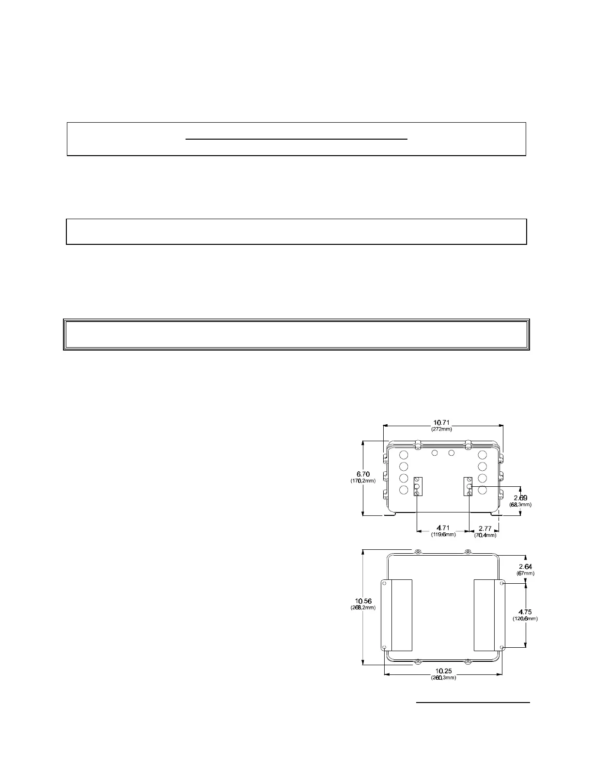
Figure 1 – Actuator Dimensions