THIS PRODUCT IS INACTIVE!
Please contact Mathers Controls for support information.
Page 8
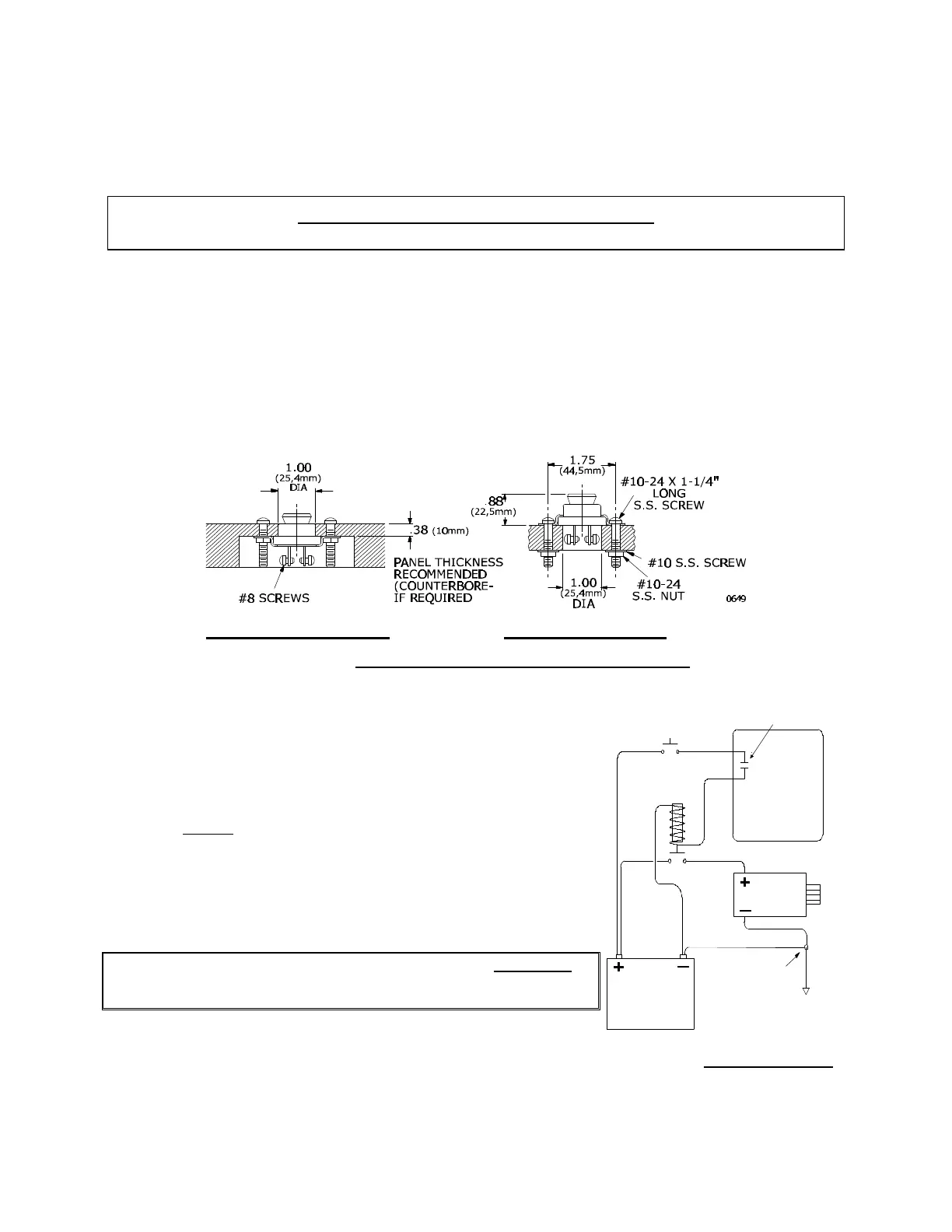
4.3 STATION TRANSFER BUTTON
One station transfer button is required at each control station.
Locate carefully so that the button is accessible, but will not be
inadvertently depressed. Use the hole template, Section 15.
The station transfer button is waterproof. There are two
methods of mounting: Surface mount or Recessed mount for
thin panels (See Figure 4).
4.4 ENGINE 'START' SWITCH
MicroCommander is interlocked to
prevent engine 'start' until power is
'ON' and the transmission is in
'NEUTRAL'. The engine 'START' signal
must be connected through the
Actuator to the starter solenoid or
relay. (See Figure 5) The interlock will
function with a 'START' signal up to 50
volts DC and 30 amp maximum.
CAUTION: The circuit board is designed for a maximum
of 30 amps 'START' signal current. Greater
current will damage the interlock circuit.
Recessed Mount Surface Mount
Figure 4 – Transfer Button Mounting Dimensions
Connections
Key
Start
Interlock
Starter
Solenoid
Actuator
Starter
Battery
DC Common
Bond
10457
Figure 5 – Start Interlock