THIS PRODUCT IS INACTIVE!
Please contact Mathers Controls for support information.
Page 66
existing installation, the 585
PROM's may need to be
changed.
A tachometer to measure
propeller RPM is helpful in
setting up the Trolling Valve
Control.
20.5.1 Adjustments
1) GENERAL
Install push-pull cable in the Trolling Valve Actuator.
Do not connect at the Trolling Valve Lever. Set DIP
Switch 6 on the Auxiliary Boards to 'ON' to enable Troll
Command.
Turn 'ON' the controls, 585 Actuator, and the 813
Trolling Valve Actuator. Take control at the remote
station and place the control lever in NEUTRAL. Make
sure the Troll Mode switch is in 'Troll' or a Jumper is
between TB5-3 and TB5-4 (see Dwg. No. 0490-B) in
0665
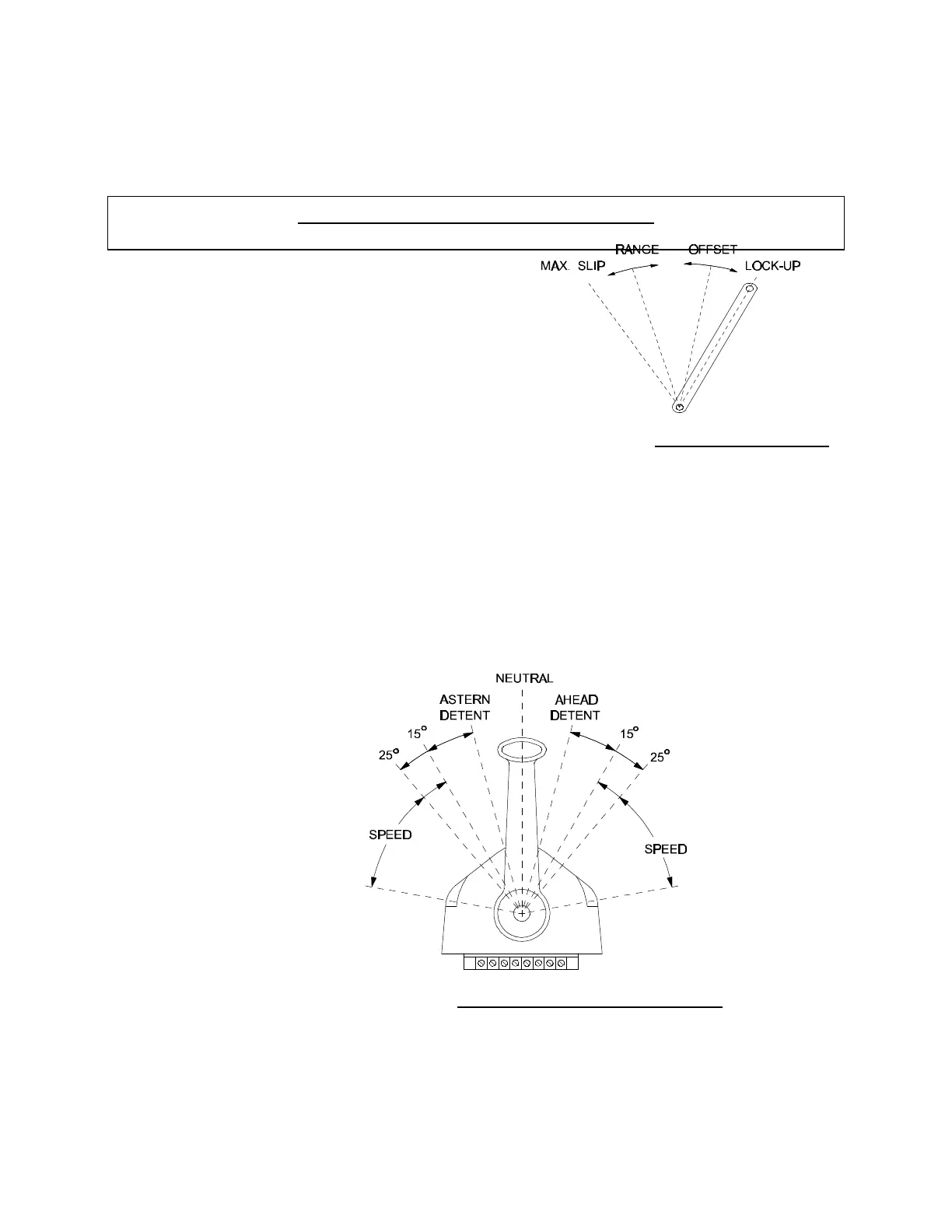
Figure 27 – Trolling Valve Lever
0666
Figure 28 – Control Head Lever Movement