THIS PRODUCT IS INACTIVE!
Please contact Mathers Controls for support information.
Page 10
4.7 CONTROL HEAD
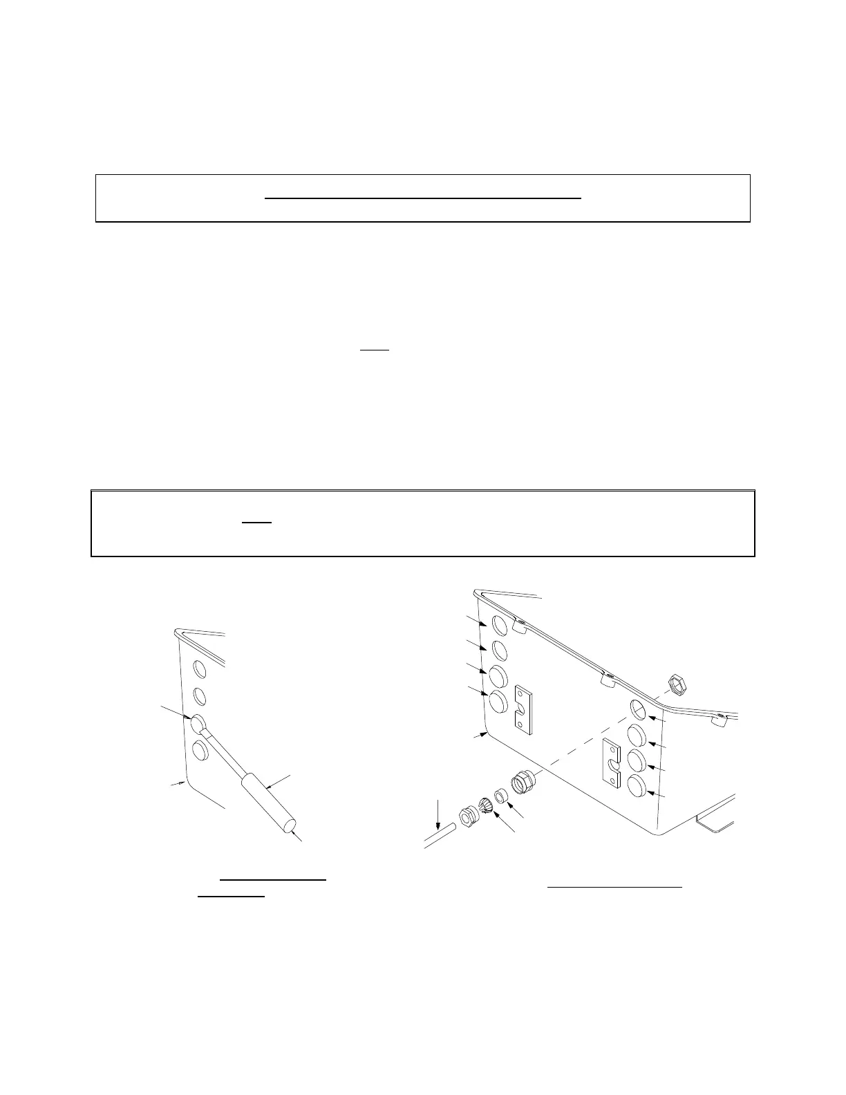
At the control head, strip back the PVC cover on the cable
approximately 2½" (63,5mm). Strip and cut off the shielding and
drain wire flush with the end of the PVC cover. The drain wire
at the control head is not connected to ground. The installer
must strip d" (9,5mm) insulation off each wire and crimp
connectors. Connections 5 and 7 of the control connector plug
are direction sensitive. The connections must be as follows:
Port Lever: Starboard Lever:
Terminal 5 Blue Terminal 5 Yellow
Terminal 7 Yellow Terminal 7 Blue
CAUTION: When making a twin screw installation, the white wire connects to Terminal 3
on the Port control only. The Starboard Terminal 3 is not connected. This is
true at all stations. See Circuit Dwg., Section 14. Cable must be supported to
eliminate load on Terminal Connections.
Station 1
Station 3
Station 5
Actuator
Electric
Cable
Cable
Grip
Seal
Start
Interlock
Troll
Figure 7 – Cable to Actuator
0653A
Figure 8 – Actuator Plug
Removal