THIS PRODUCT IS INACTIVE!
Please contact Mathers Controls for support information.
Page 13
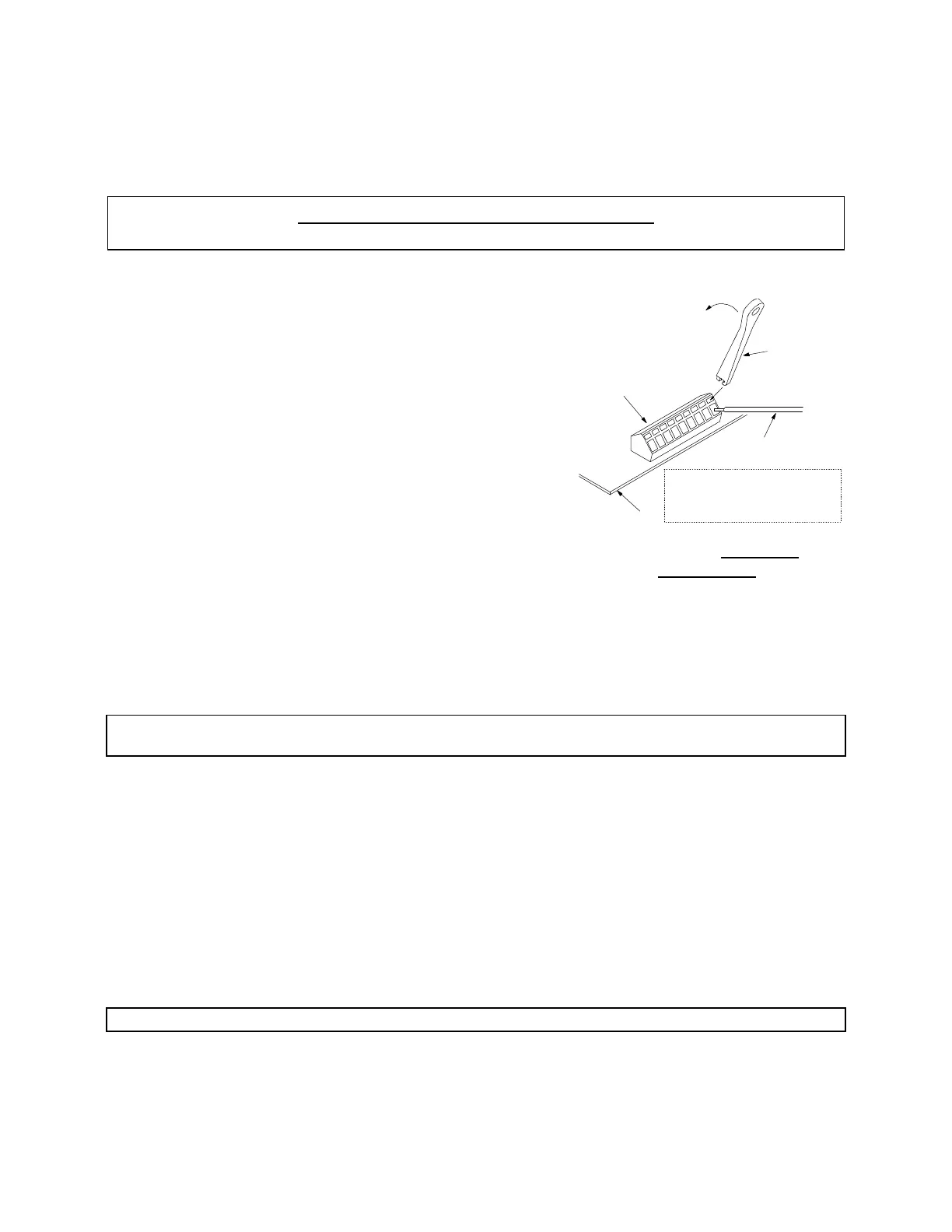
is included with each Actuator. It is
taped to the relay on the circuit
board. It is used to depress the
spring lock for the individual wire
connection to the terminal strip.
(See Figure 11) The shielding drain
wire (bare wire) must be connected
to terminal 8 on the terminal strip,
and must not come in contact with
the frame. Feed through a little
slack cable and tighten the cable
grip on the eight (8) conductor
cable. The other stations eight (8)
conductor cables are brought in the
same way and are connected to the
appropriate terminal. (See Figure 9)
Secure the cable to the frame using
tie wraps provided.
NOTE: A jumper is required between terminals 5 and 6 on all unused stations on
the circuit board.
4.10 CONNECT DC POWER TO ACTUATOR
When connecting the DC power cable to the Actuator be sure the
power is 'OFF'. The (+) positive lead (red with purple stripe)
connects the + DC power source to the Actuator. (See Figure 3)
The (-) negative lead is black. The ferrite bead is fed onto the
power cable before entering the Actuator. Tie wrap the power
cable to the frame and tighten the cable grip.
4.11 INSTALL START INTERLOCK CABLE
NOTE: Maximum current rating of interlock relay is 30 amperes.
The start interlock cable, two (2) wires are yellow with a red
stripe. Remove the key start lead at the start solenoid. (See
Figure 5) Connect one (1) yellow with red striped wire to this
Terminal Strip
WAGO
Tool
One Wire of
Forward to Release Spring
Lock and Insert Wire End.
0656
Figure 11 – Terminal
Connection