THIS PRODUCT IS INACTIVE!
Please contact Mathers Controls for support information.
Page 9
4.5 ENGINE 'STOP' SWITCHES
Engine 'STOP' switches are required at all remote control
stations. The 'STOP' switches are installer supplied.
WARNING: Each remote station must have some method to stop the engine or
engines. This requirement must be followed or warranty is canceled.
4.6 EIGHT-CONDUCTOR CABLE
Install the eight-conductor electric cable (two cables if twin
screw) between each control head and the appropriate Actuator.
There can be as many as five remote stations. Label each
eight-conductor cable at both ends with the station it connects,
and port or starboard engine control.
The eight-conductors in the electric cable are color coded. Each
conductor shall be installed so that it is protected from physical
damage. Conductors shall be supported by clamps or straps
not more than 18" (0,5m) apart, unless contained in a conduit.
(Reference Section 11.)
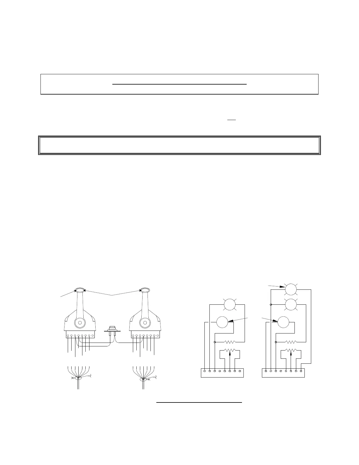
Port
Station
Transfer
Button
Violet
Violet
Black
Brown
Red
Orange
Blue
Green
Yellow
Black
Brown
Red
Orange
Yellow
Green
Blue
Orange
White
Orange
1234567812345678
Single
Dual
Red
Tone
Red
0651-585
Figure 6 – Control Head Connections