THIS PRODUCT IS INACTIVE!
Please contact Mathers Controls for support information.
Page 59
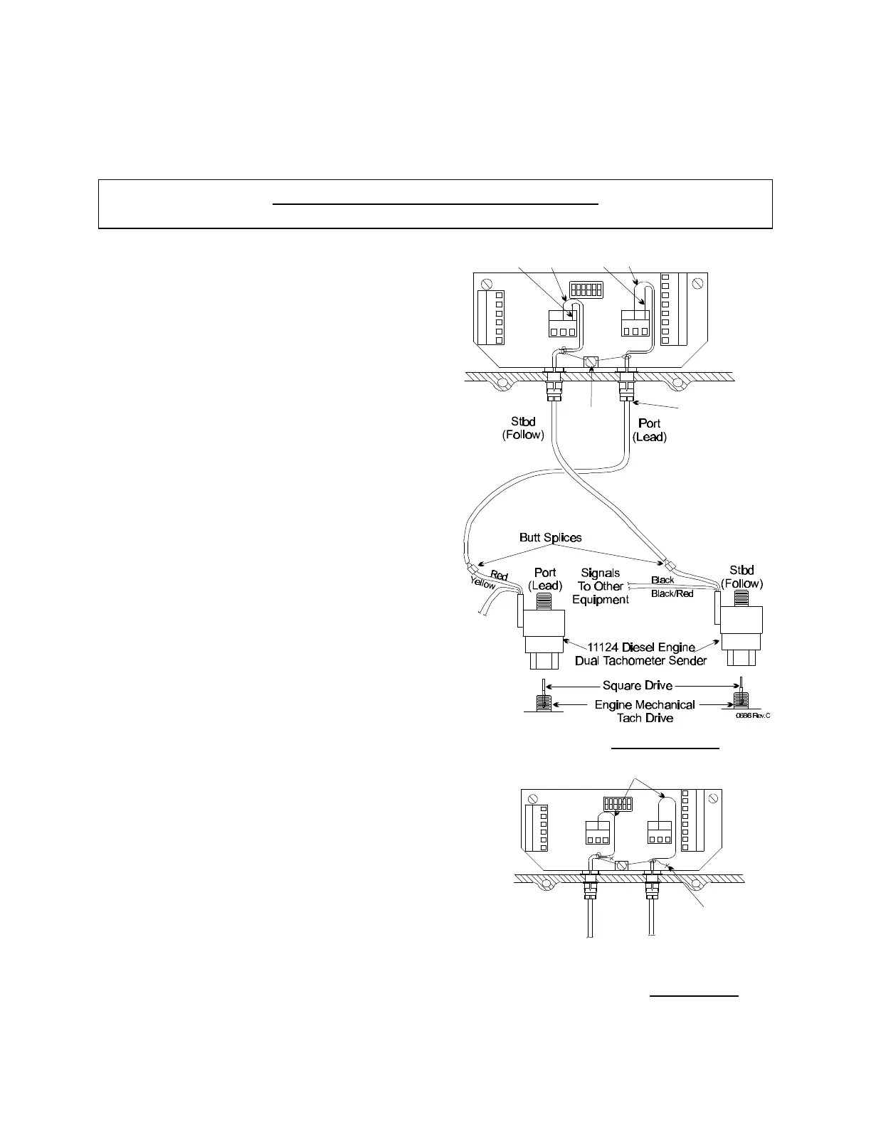
F) The 1135 Starboard
Auxiliary Board requires an
electric pulse input in
proportion to RPM from
each engine. The electric
pulse can come from a
tachometer pulse
generator driven by the
engine mechanical tach
drive. The electric pulse
can also come from a
magnetic pickup mounted
in proximity of the flywheel
ring gear. The 1135-1,
Starboard Auxiliary Board,
is required when gasoline
engine speed pulses are
taken from the point side
of the coil. See Figure 25
and Figure 26.
G) To verify senders are
working properly: at
'IDLE', between Terminal 2
and 3 on TB2 and TB3 you
should see approximately 3.Ø
AC volts, increasing with RPM.
H) Synchronization will occur
automatically when both control
levers are 'AHEAD', above 10%
of speed range, and within 15%
of equal RPM. To check
synchronization operation tied to
the dock, disconnect the shift
push-pull cables at the
SWITCH
TB4
TB2
TB1
TB3
123 123
1
2
3
4
5
6
8
7
6
5
4
3
2
1
1
OFF
Are Not
Polarized
Follow
Shield
Drain
Figure 25 – Diesel Engine
SWITCH
TB4
TB2
TB1
TB3
12 3
1 23
1
2
3
4
5
6
8
7
6
5
4
3
2
1
1
OFF
Stbd
(Follow)
Port
(Lead)
0687
1027 Gas Engine Signal Kit
Figure 26 – Gas Engine