Matrox Mura Display Wall – User Guide 21
Using a multi-display layout with an uneven number of columns
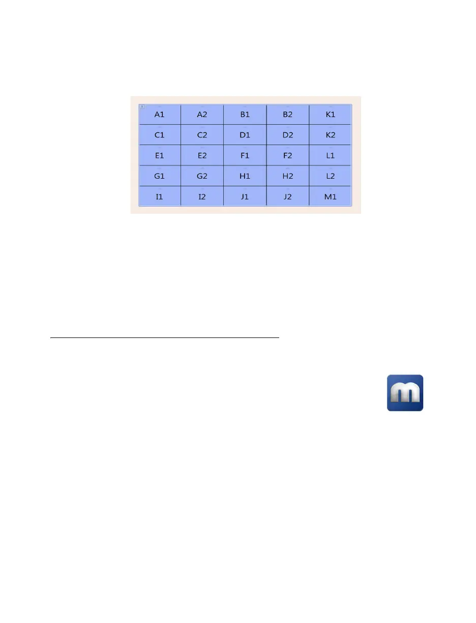
This multi-display layout shows a 5
×
5 display wall. In this case, monitors are paired but don’t follow
each other sequentially from left to right. In this case, the GPUs associated with the last card (
K1
,
K2
,
L1
,
L2
,
M1
) are placed in the last column of the layout.
Depending on your installation and connection, you may need to manually rearrange the outputs of
your multi-display layout in PowerDesk to match the physical layout of your display wall.
For more information on setting up multiple displays, see “Configuring your display wall layout”,
page 55.
After planning your output layout, you’re ready to install your cards (see “Installing your Matrox
cards”, page 24).
Planning the output layout of C-Series cards
Using PowerDesk to manage your multi-display layout
In a multi-card setup, PowerDesk assigns letters to the GPU and numbers to the outputs
associated with that GPU. Each card is identified with a unique GPU. C900 cards have
three (3) outputs (
1
,
2
, or
3
) using one or three connectors each. Output
1
uses
connectors
1
,
2
, and
3
. Output
2
uses connectors
4
,
5
, and
6
. Output
3
uses connectors
7
,
8
, and
9
.
C680 cards have six (6) outputs with a single connector each.