Routing input signals to Matrox Iris GTR 109
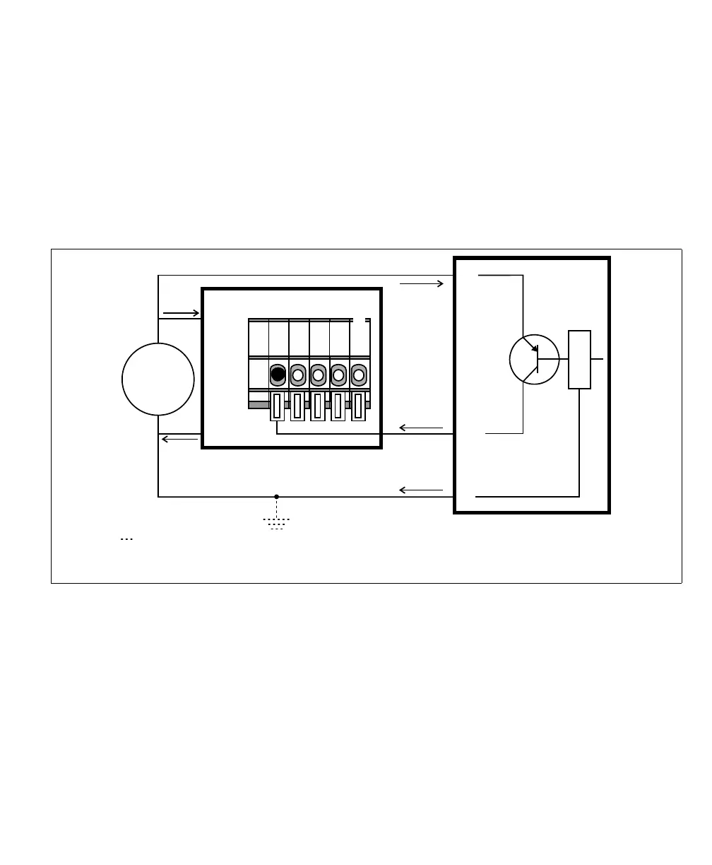
Connecting a sourcing output device to a Matrox Iris GTR auxiliary input
signal
If connecting to a sourcing output of a third-party device, the input common
should provide the common return path for the circuit. To provide the common
return path through the Matrox Iris GTR breakout board (internally), set the
IN_COM_TERM switch (SW6[4]) to ON and the IN_COM selector switch
(SW2) to -VDC. Then, connect the input connector (J5) to your third-party
device as follows:
Equivalent circuit only
24V
+
–
+ VDC
- VDC
OUT
+V
-V
Sourcing device
Matrox Iris GTR breakout board
Sinking configuration
Input connector (J5)
IN3
IN_COM*
The ground depicted is optional because the auxiliary input signals are optically isolated.
In this example, IN_COM_TERM switch is set to ON and the IN_COM selector switch*
(SW2) is set to -VDC; so the IN_COM wire-terminal is not externally connected.