110 Appendix F: The Matrox Iris GTR breakout board
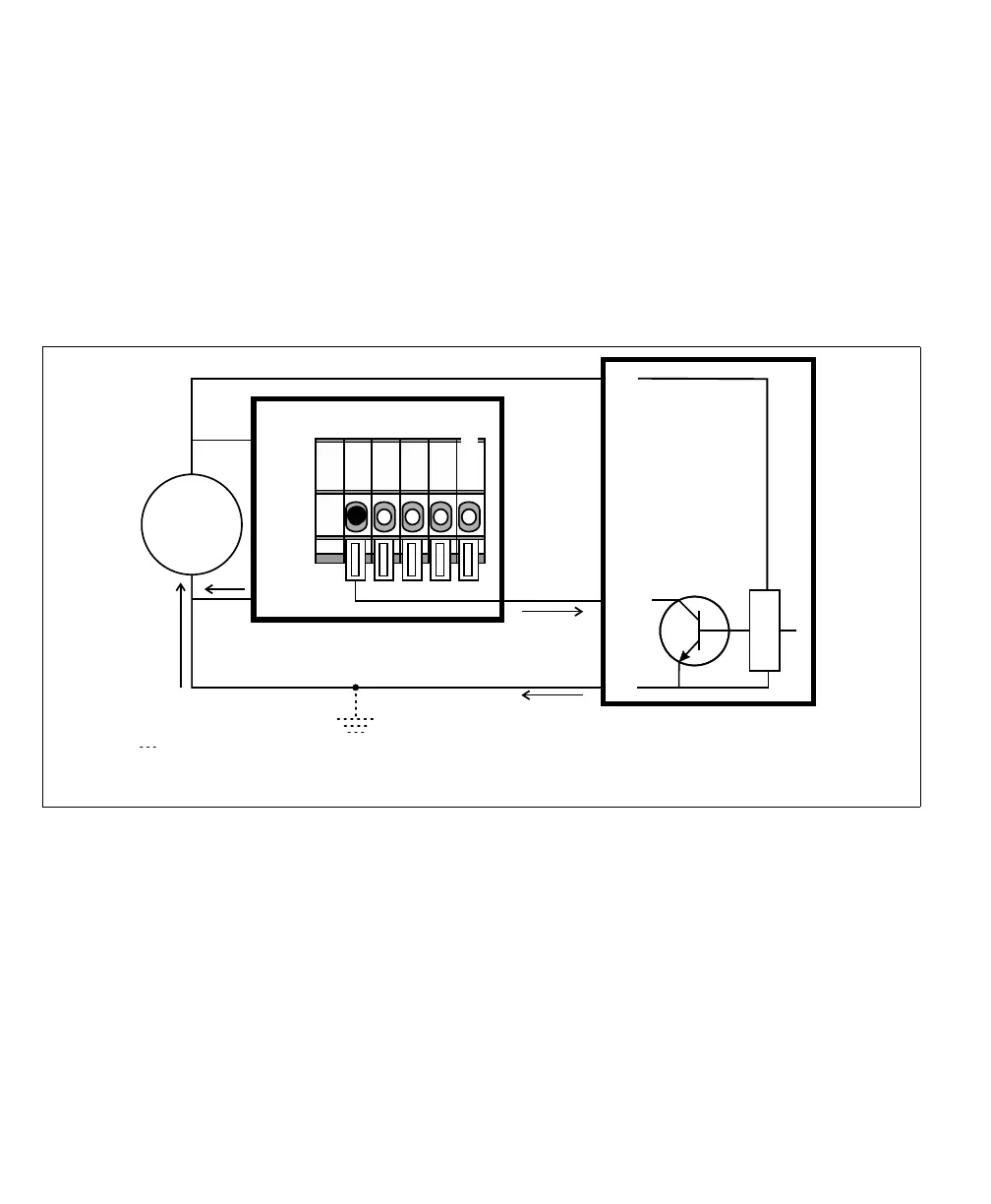
Connecting a sinking output device to a Matrox Iris GTR auxiliary input
signal
If connecting to a sinking output of a third-party device, the input common should
be connected to a voltage source so that the auxiliary input signal acts as a sourcing
input. To have the Matrox Iris GTR breakout board (internally) provide the
voltage source for the input common, set the IN_COM_TERM switch (SW6[4])
to ON and the IN_COM selector switch (SW2) to +VDC. Then, connect the
input connector (J5) to your third-party device as follows:
Equivalent circuit only
Input connector (J5)
24V
+
–
+ VDC
- VDC
AUX IN_3
OUT
+V
-V
Sinking device
Matrox Iris GTR breakout board
Sourcing configuration
IN3
IN_COM*
The ground depicted is optional because the auxiliary input signals are optically isolated.
In this example, IN_COM_TERM switch is set to ON and the IN_COM selector switch*
(SW2) is set to +VDC; so the IN_COM wire-terminal is not externally connected.