Routing Matrox Iris GTR auxiliary output signals 121
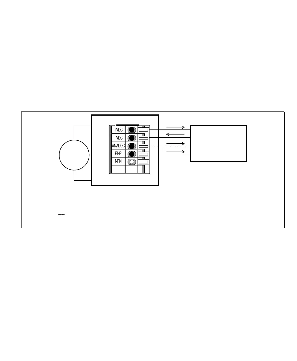
Connecting Matrox Iris GTR auxiliary output signal 0 to a sinking lighting
controller (PNP pin)
If your lighting controller has a PNP pin (sinking input signal), it expects to be
connected in a PNP topology, whereby the connected, controlling auxiliary output
signal sources the current and the input pin sinks the current. To do so, route
auxiliary output 0 to the PNP wire-terminal by setting the Output-to-ICS3
selector switch (SW8) to PNP, and activate the internal pullup for auxiliary output
signal 0 by turning output pullup resistor switch 3 (SW6[3]) to ON. Then,
connect the ICS3 connector (J7) to your third-party device as follows:
❖ Note that, when connecting to the PNP wire-terminal, the voltage observed on
the pin is inverted when compared to the voltage observed on the auxiliary output
signal pins (OUT0, OUT1, and OUT2). When the auxiliary output signal is set
to On, the signal on the PNP wire-terminal is high; when it is set to Off, the signal
on the PNP wire-terminal is low.
When the Matrox Iris GTR breakout board supplies the power to the lighting
controller, verify that the total power required by the lighting controller and your
smart camera does not exceed the rating of your power supply. If the lighting
controller’s power requirements exceed the 1.5 A provided by your Matrox
Iris GTR breakout board, connect the lighting controller’s 24 VDC directly to
the power supply instead of using the +VDC wire-terminal (J7[+VDC]). For more
information on current consumption of your Matrox Iris GTR breakout board,
Equivalent circuit only
Sinking lighting controller
24V
+
–
Matrox Iris GTR breakout board
Sourcing configuration
-VDC
+VDC
Power
GND
PNP/Active high trigger
0-10V Analog Control
* The Output-to-ICS3 selector switch must be set to PNP and the output pullup
resistor switch 3 (SW6[3]) must be set to ON.
Optional, connect only if your lighting controller device requires a reference
control (dimmer/intensity control).
*
ICS3 connector (J7)