122 Appendix F: The Matrox Iris GTR breakout board
refer to Electrical specifications subsection in Appendix B: Technical reference. For
the current consumption of your lighting controller, refer to its associated
documentation.
❖ Note that in this configuration, auxiliary output signal 1 and auxiliary output
signal 2 are still available via the Matrox Iris GTR breakout board.
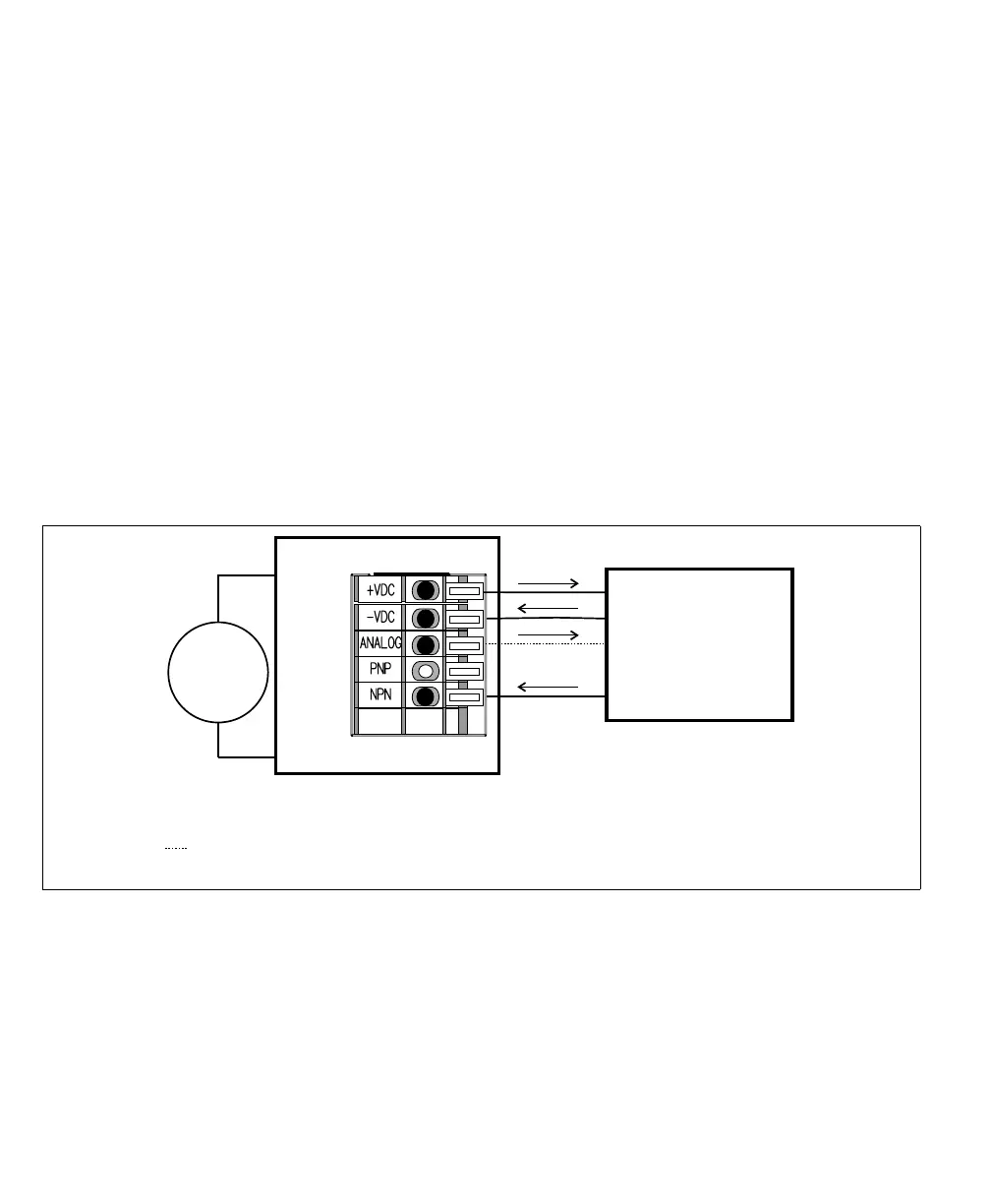
Connecting Matrox Iris GTR auxiliary output signal 0 to a sourcing lighting
controller (NPN pin)
If your lighting controller has an NPN pin (sourcing input signal), it expects to
be connected in a NPN topology, whereby the connected, controlling auxiliary
output signal sinks the current and the input pin sources the current. To do so,
route auxiliary output 0 to the NPN wire-terminal by setting the Output-to-ICS3
selector switch (SW8) to NPN. Then, connect the ICS3 connector (J7) to your
third-party device as follows:
Equivalent circuit only
24V
+
–
Matrox Iris GTR breakout board
Sinking configuration
-VDC
+VDC
Sourcing lighting controller
Power
GND
NPN/Active low trigger
0-10V Analog Control
ICS3 connector (J7)
*
* The Output-to-ICS3 selector switch must be set to NPN.
Optional, connect only if your lighting controller device requires a reference
control (dimmer/intensity control).