46 Chapter 2: Powering and connecting to your Matrox Iris GTR
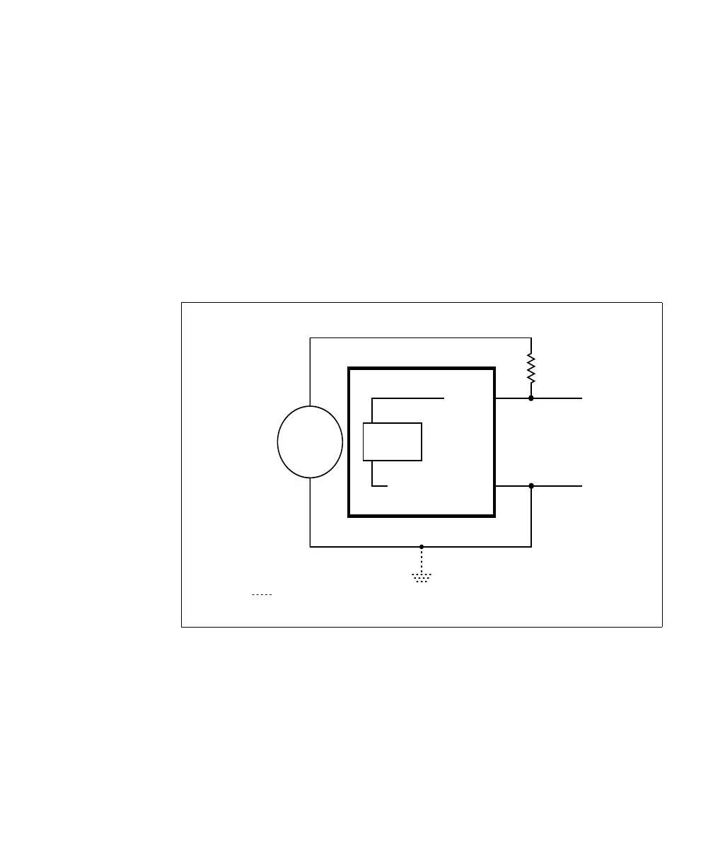
Pullup circuitry In some cases, you must add pullup circuitry to connect an output device to an
auxiliary input signal; specifically, you must attach an external pullup resistor
between the voltage source and the AUX_IN pin.
This is required when you connect the AUX_IN_COMMON pin to the electrical
return path and the third-party output device is in a sinking configuration. In this
case, select a resistor value that will not overcurrent the output device and instead
provide just enough current and voltage to your Matrox Iris GTR auxiliary input
signals, according to the Electrical specifications subsection in
Appendix B: Technical reference. Note that you should use a resistor with an
appropriate power rating for your circuit.
Equivalent circuit only
Connection required if using external pullup circuitry
24V
Sensing
Circuit
AUX IN_
AUX IN_COMMON_
+
-
Optional because the auxiliary input signals are optically isolated.