Connecting to the auxiliary I/O interface 47
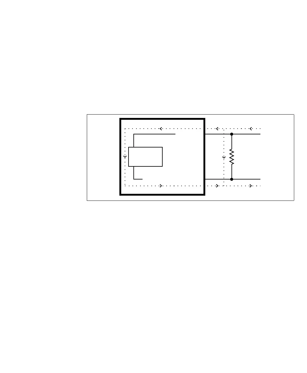
Bleeding resistor By default, if properly configured, the current should flow from the AUX_IN pin
to the AUX_IN_COMMON pin (when connected to a sourcing device), or from
the AUX_IN_COMMON pin to the AUX_IN pin (when connected to a sinking
device). In some cases, the amount of current going through the sensing circuit is
insufficient for the connected output device to match its minimum current
requirement when the device is in an on or off-state, depending on the
configuration of the circuit. To boost the flowing current, connect a 2.2 kOhm
external bleeder resistor between the AUX_IN and AUX_IN_COMMON pins.
For example:
About the
connections in the
following
subsections
The following subsections detail how to connect the most common third-party
devices to the Matrox Iris GTR auxiliary input signals.
Note that Matrox Iris GTR auxiliary input signals are optically isolated. Ground
is only shown in the following subsections for reference, in case you need to
reference your return path to ground.
Power, as depicted in the following diagrams, represents a nominal voltage of 24 V
(+/- 10%). For minimum and maximum voltage requirements, refer to the
electrical specification of the opto-isolated auxiliary input signals, in the Electrical
specifications subsection in Appendix B: Technical reference.
The signal names in this section are shortened to fit within the diagrams: from
M_AUX_OPTOIND_INn to AUX_IN; and from
M_AUX_OPTOIND_IN_COMMON to AUX_IN_COMMON.
Equivalent circuit only
External
Bleeder
Resistor
Sensing
Circuit
AUX IN_
AUX IN_COMMON_