Installation Comet Executive Gas
2-2
2.1 Site and Utility
Requirements
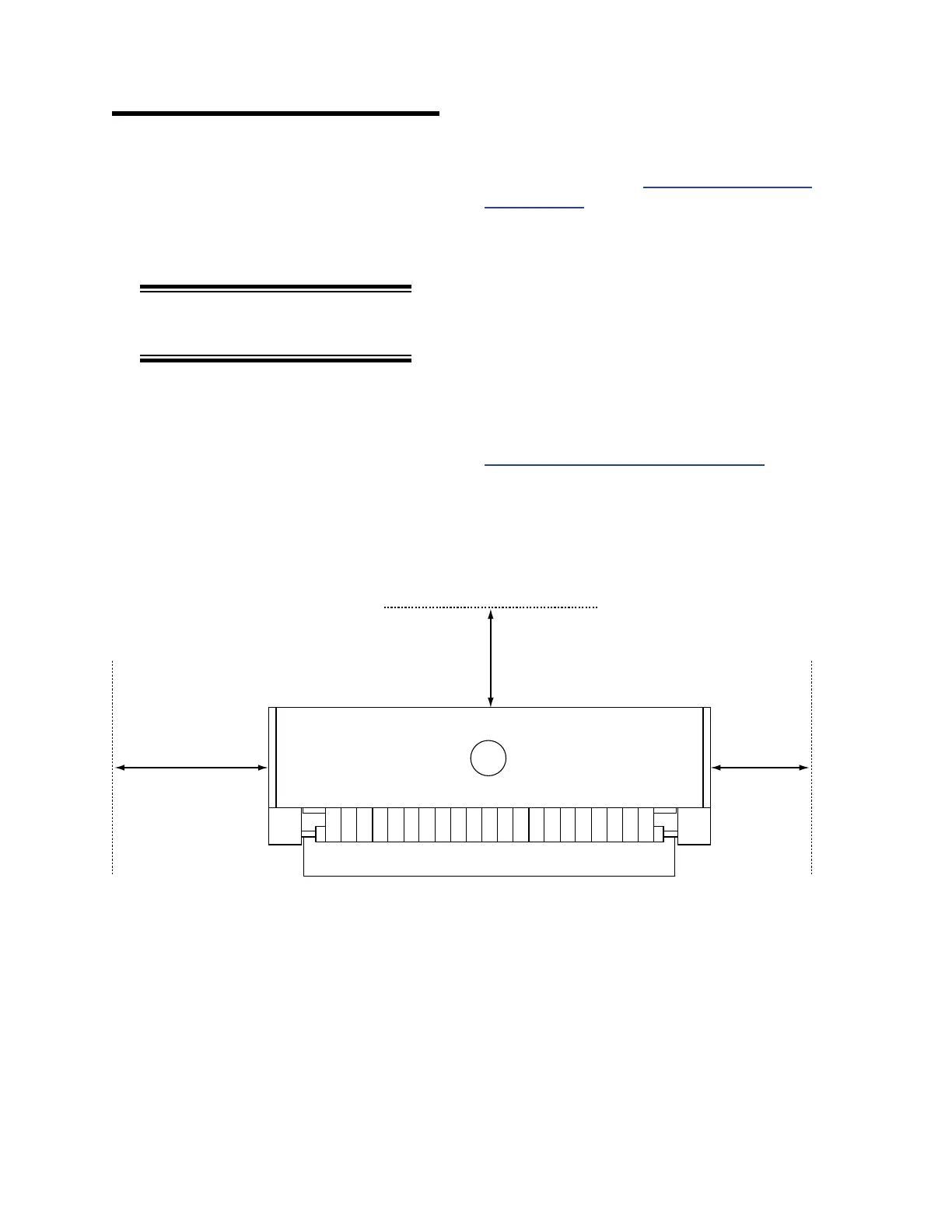
Figure 2-1 shows the clearance requirements
for the unit. These are the minimum dimensions
recommended for ecient production, service,
and maintenance access.
NOTE: The location of the unit
is extremely important.
It is strongly recommended that sufficient
clear space be provided to allow for removal of
the gas burner assembly from the left endframe
for service, if necessary. If this clearance is not
possible, additional clearance to the front or rear
of the unit should be provided so the unit can be
rotated.
The site should have a relatively level,
sturdy floor capable of supporting the unit’s
weight without signicant exing. For weight
specications, refer to APPENDIX: Technical
Specications.
Shimming of the endframes is generally
needed to level the unit. No special foundation,
floor grouting, or installation of anchors is
required. However, oor grouting or installation
of anchors may be required to comply with local
codes or aboard a ship.
A short run of 8” (203 mm) diameter vent
ducting must be supplied locally for the exhaust
blower and canopy. Adequate ventilation
is required. For more information, refer to
Ventilating the Work Area on page 2-7.
Figure 2-1: Recommended clearances for installation.
18”
(460 mm)
18”
(460 mm)
Ironing Cylinder Length
plus 24” (610 mm)