Installation Comet Executive Gas
2-8
Electrical Connection
CAUTION
The incoming electric
power service must match
the specic electrical
requirements shown
on the nameplate.
The nameplate (Figure 2-2), located on the
front of the left endframe, shows the electrical
requirements of the unit. All labor and materials
required to bring the electrical service to the unit
are a local responsibility.
All electrical wiring must comply with local
codes, and a qualied electrician should size the
wiring.
Refer to the nameplate to determine the power
supply requirements. If high or low voltage
is suspected, check the electrical service to
determine the actual voltage conditions.
Improper or uctuating voltage will cause
the safety systems to interrupt the burner system
operation, possibly damage motors and other
electrical system components, and void the
factory warranty.
NOTE: A fused, main disconnect
switch has been incorporated into
the right endframe door. Check
local regulations to determine
whether a separate external fused
disconnect switch is still required.
Follow local codes at all times.
Sail Switch and Exhaust Blower Motor
Connection
NOTE: All material for wiring
the exhaust blower motor and sail
switch must be locally supplied.
Check local regulations to
determine requirements. Follow
local codes at all times.
Required Tools
Screwdriver
Wire cutter/stripper
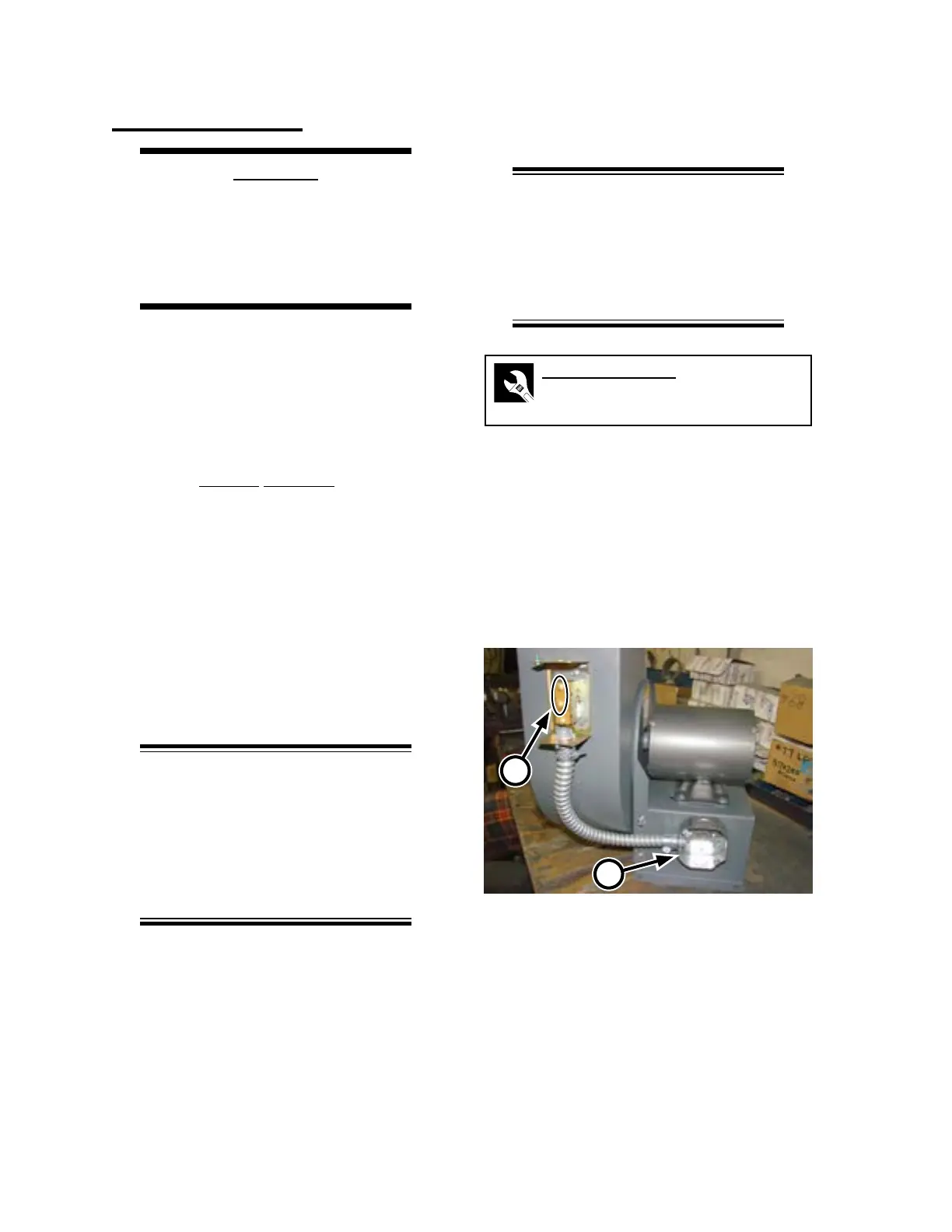
1. Remove the sail switch and wiring box
covers.
2. Connect a wire to each of the upper two
terminals, labeled R and B (Figure 2-7, A)
and route them through the greeneld and
into the wiring box (B).
3. Replace the sail switch cover.
Figure 2-7: Connect the sail switch wires to the
terminals labeled R and B and bring
into the wiring box.
A
B