Operating Guidelines Comet Executive Gas
3-4
3.2 Operating Controls
All operating controls are externally mounted
on the front of the endframes and clearly marked
with functional names. References to these
functions are capitalized in this instruction manual
for easy identication. Detailed descriptions are
given in the following paragraphs.
Control locations include:
• Right Endframe Controls
• Left Endframe Controls
Right Endframe Controls
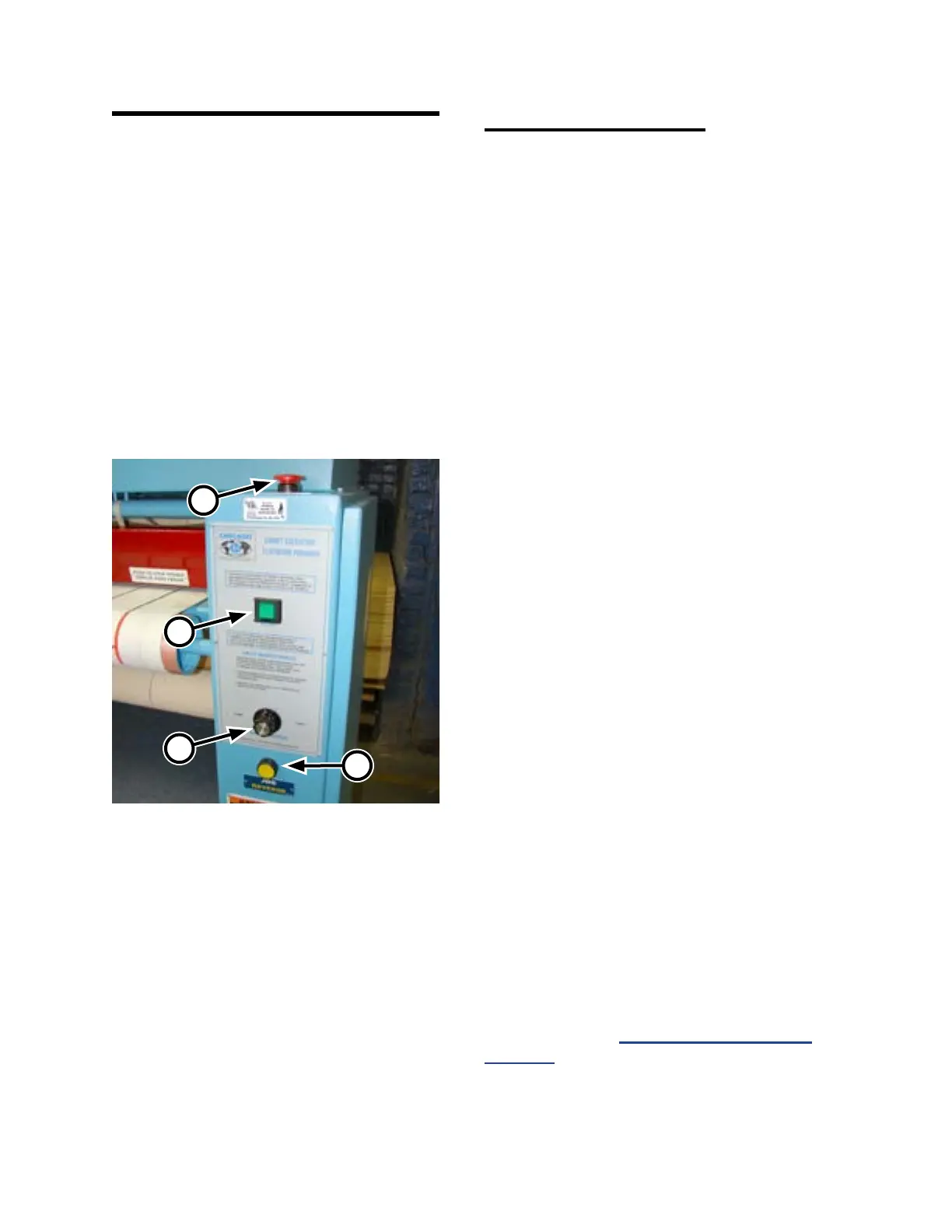
The following operating controls (Figure 3-6)
are located at the front of the right endframe:
• STOP button (A)
• START button (B)
• SPEED CONTROL knob (C)
• JOG REVERSE button (D)
STOP button (A):
Provided to help ensure operator safety and
to prevent damage to the unit. There are four red
safety STOP buttons—one on the front and back
of each endframe.
Pressing any of the four red safety STOP
buttons immediately stops the heating system
and all rotating parts, leaving the unit in the
standby state.
START button (B):
Begins the start-up and operation of the unit.
A green indicator lamp, located under the switch
surface, lights when the green START button is
pushed.
This indicates that power is connected to the
motors. All rotating parts, including the ironing
cylinder, feed ribbons, and return ribbons begin
to move.
SPEED CONTROL knob (C):
Controls the speed of the unit. Turning the
SPEED CONTROL knob clockwise causes
atwork to be processed at a faster speed. Turning
the SPEED CONTROL knob counterclockwise
causes atwork to be processed at a slower speed.
For more information on determining the
proper operating speeds for dierent types of
flatwork, refer to Processing Standards on
page 3-15.
Figure 3-6: Right endframe control panel.
C
B
D
A