Comet Executive Gas Installation
2-9
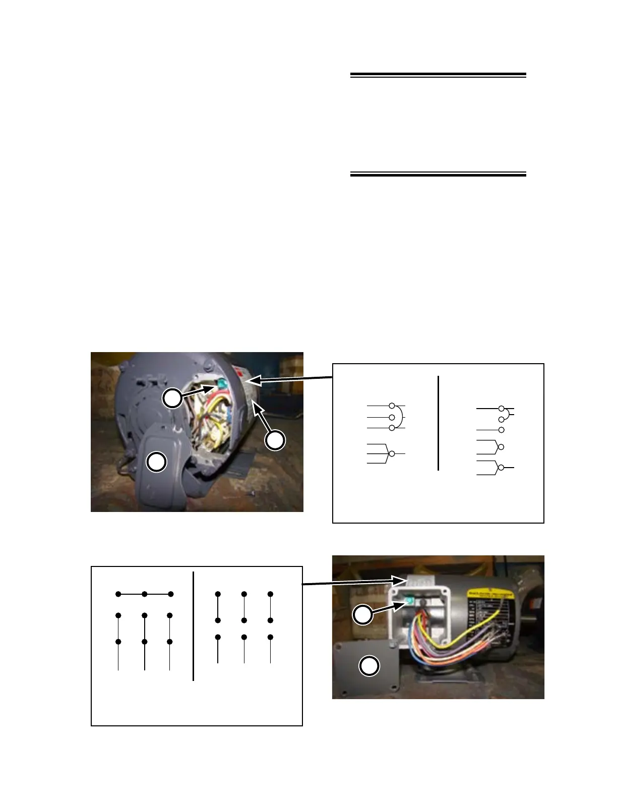
4. Remove the wiring box cover to the ex-
haust blower motor (Figure 2-8, A/Figure
2-9, A).
5. Bring the wires for the sail switch into the
wiring box and attach the electrical con-
nection to the box.
6. Use wire nuts to securely connect to each
sail switch wire; then, replace the wiring
box cover.
NOTE: If local codes permit,
consider routing the exhaust
blower wires into the sail switch
wiring box and then bringing a
single connection over to the
ironer.
7. Bring the wires for the exhaust blower into
the wiring box and attach the electrical
connection to the box.
8. Follow the label on the motor case (Figure
2-8, B for single phase; Figure 2-9, B for
3-phase) to wire for high or low voltage
as appropriate. Make sure to connect the
grounding wire to the lug (C).
9. Replace the wiring box cover(s).
Low Voltage High Voltage
Blue
Red
Black
White
Yellow
Brown
Line
1
3
4
5
6
To reverse: Interchange
Line
Blue
Red
Orange
Black
White
Yellow
Line
1
4
5
6
Line
A
C
B
Figure 2-8: Wiring for single phase exhaust
blower motor.
A
C
Line
123
456
789
123
456
789
Line
Interchange any two line wires
Figure 2-9: Wiring for 3-phase exhaust blower
motor.