Installation Comet Executive Gas
2-10
10. The main disconnect switch is located on
the right endframe door. Turn it to the OFF
position (Figure 2-10, A).
11. Turn the door latch (Figure 2-10, B) on
the right endframe door and open the door.
12. Route the electrical connections for the
sail switch and exhaust blower motor to
the electrical box.
13. Properly secure the electrical connections.
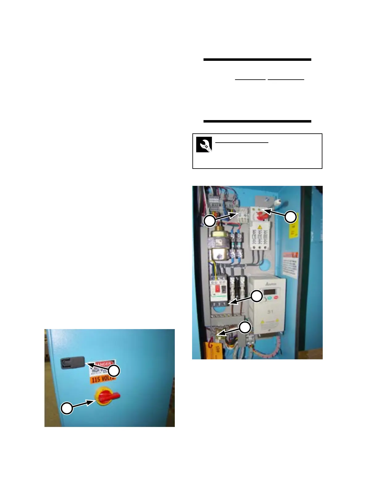
14. The electrical connections for the exhaust
blower motor are made in the electrical
panel:
a) Connect the power wires for the ex-
haust blower motor to the terminals at
the bottom of the canopy motor protec-
tor (Figure 2-11, A) as follows:
• 3-Phase: 2, 4, and 6.
• Single phase, 230V: 2 and 6
• Single phase, 115V: 4 and 6.
b) Connect the green ground wire to the
grounding block at the top of the elec-
trical panel (Figure 2-11, B)
c) Remove the jumper wire connected
to terminals 5 and 6 (Figure 2-11, C)
and connect the two red wires for the
exhaust blower sail switch.
Figure 2-10: The main disconnect switch is located
on the right endframe door.
B
A
Main Power Connection
WARNING
Only a qualied electrician
should make the electrical
connections to the unit.
Improper installation could
result in serious injury.
Required Tools
Allen wrench: 3/16”
Screwdriver
Wire cutter/stripper
Figure 2-11: Exhaust blower connections.
C
B
D
A