Alterations reserved
Version 05/2008
Operating Manual B21-C - en
Page 79
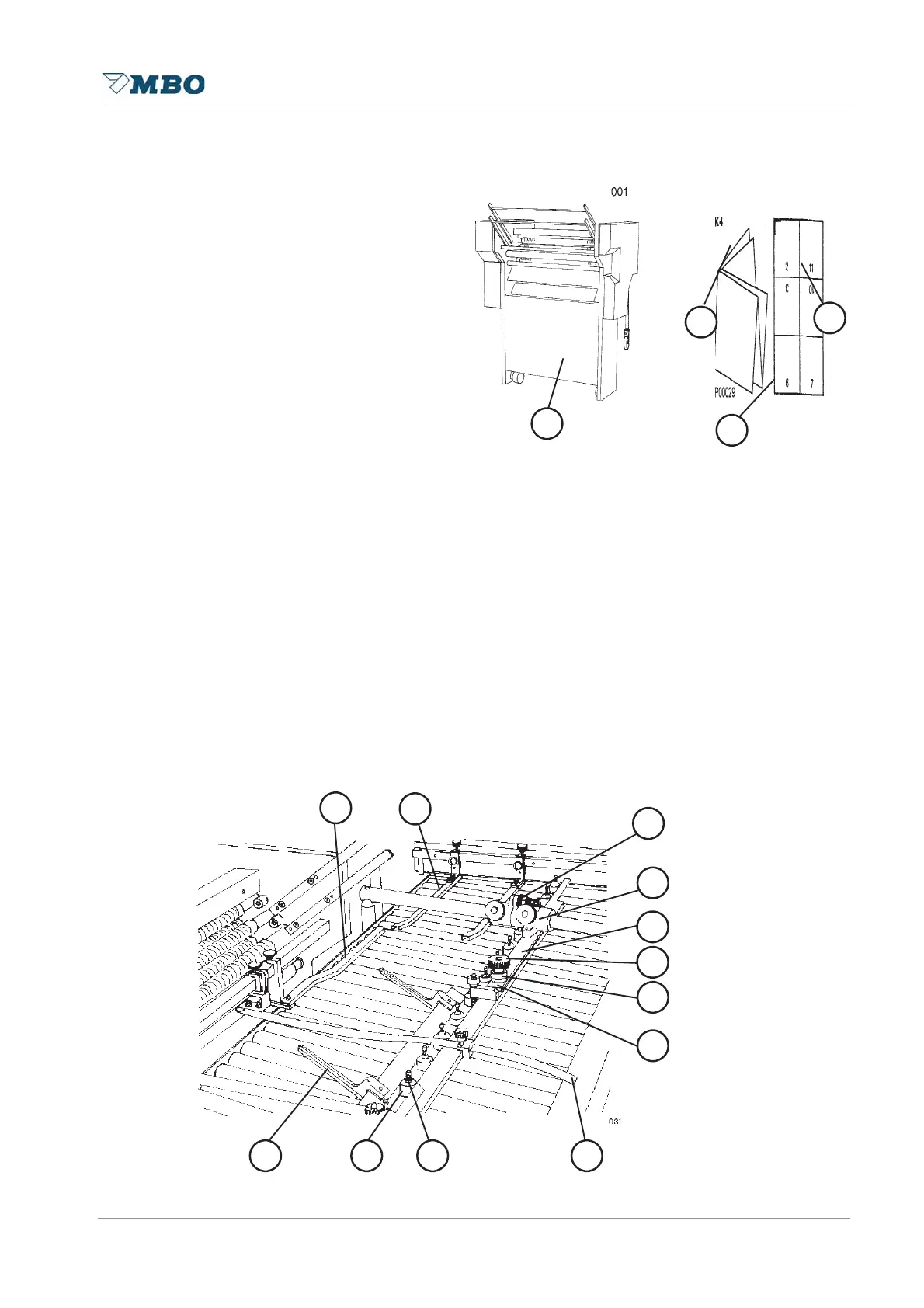
B 6.0 Mobile buckle folding unit
6.1 Installation
This unit 4 is normally placed crosswise
to the previous folding unit. It is locked
through a brake at foot 6.
The infeed height of the register table 5
or its inclination may also be carried out
through this foot, whereby knurled screw
7 is used for locking purposes.
6.2 Setting and sheet transportation
Set the sidelay 5 to the appropriate sheet size through the setting elements 4.
Fine adjustments can be made via knurled nut 3. The angle of the sidelay to the foldrollers can be
changed via the knurled screw 6 or through the excenter 7. Please note that a scale 8 has been
fixed onto the sidelay.
The sheet should run with its end as close as possible to the edge of the mobile folding unit. In
order to avoid any lifting of the sheet at the exit of the previous folding unit, smoother tapes 9
should be used. A safe infeed of the sheets underneath the ball rails are achieved if you use sheet
holders 14. Depending on the thickness of product, you may also adjust the infeed plate 1, which
may be carried out by the knurled screws .
In order to avoid any lifting of the sheets on the unit and to ensure a proper infeed of the sheet
into the foldroller, you may also use smoother bars 1 and 2. The height of these smoother bars is
adjustable.
Plastic or steel balls which are positioned in a ball holder are used to transport the sheets on the
register table (consider the inclination). The weight or quantity of these balls depend on the weight
of the paper.
4
6
7
5
1
1
2
3
4
5
6
7
1
1
9
8