CONTENTS
AVTM246004 BITE 2/2P Rev 4 July 2011
iii
APPENDIX B: REPLACEABLE PARTS...................................................................................... 97
Catalog Numbers 246002B and 246004...................................................................................... 97
Catalog Numbers 246002B and 246004...................................................................................... 98
How to Order Replaceable Parts for the BITE 2/2P.................................................................... 98
GLOSSARY .................................................................................................................................. 99
INDEX......................................................................................................................................... 101
Figures
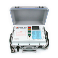
Figure 1-1: BITE 2 instrument......................................................................................................... 5
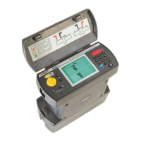
Figure 1-2: BITE 2P instrument ...................................................................................................... 6
Figure 3-1: BITE 2 transmitter ...................................................................................................... 14
Figure 3-2: BITE 2P transmitter .................................................................................................... 16
Figure 3-3: Voltage Selector Card Orientation............................................................................... 17
Figure 3-4: Receiver controls, connectors, and indicators.............................................................. 18
Figure 3-5: Flowchart for Receiver menus..................................................................................... 20
Figure 3-6: Flowchart for Receiver menus..................................................................................... 21
Figure 3-7: Flowchart for Receiver menus..................................................................................... 22
Figure 3-8: Receiver menu ............................................................................................................ 23
Figure 3-9: Receiver RESET switch.............................................................................................. 24
Figure 4-1: Receiver controls, connectors and indicators............................................................... 28
Figure 4-2: Initialization screens ................................................................................................... 29
Figure 4-3: Scanning test information............................................................................................ 31
Figure 4-4: Receiver controls, connectors, and indicators.............................................................. 35
Figure 4-5: BITE 2/2P transmitter connected to the battery ........................................................... 36
Figure 4-6: Receiver and potential probe positioned on top of battery cell terminals...................... 39
Figure 4-7: Receiver and potential probe positioned on top of battery strap terminals.................... 40
Figure 5-1: Reversing the current source leads on a single string of cells when a high
or low current message is displayed. ......................................................................... 48
Figure 5-2: Sectioning a battery system greater than 275 V........................................................... 50
Figure 5-3: Sectioning a parallel string of cells.............................................................................. 52
Figure 6-1: Exporting data to a PC ................................................................................................ 57
Figure 6-2: Printing test results...................................................................................................... 58
Figure 6-3: Deleting test results from the Receiver ........................................................................ 60
Figure 7-1: Generic curve of impedance vs. cell life...................................................................... 64
Figure 9-1: RTC battery "piggybacks" the system battery.............................................................. 77
Figure 9-2: BITE 2 transmitter secondary fuses (front view) ......................................................... 83
Figure 9-3: BITE 2P transmitter secondary fuses (front view) ....................................................... 86
www.GlobalTestSupply.com
Find Quality Products Online at: sales@GlobalTestSupply.com