HARDWARE MANUAL Document reference MAMPS-HW/E
VM600 machinery protection system (MPS) Edition 18 - March 2022
4-8
Inputs and outputs
MPC4 / IOC4T CARD PAIR
signals from accelerometers, velocity transducers, proximity probes or dynamic pressure
probes are handled. Hardware associated with the sensors such as signal conditioners and
optional safety barriers or galvanic separations are not implemented within the MPS, but
externally.
Both voltage-based and current-based input signals are accepted by the MPS. Depending on
the sensor and signal conditioner type used, 2-wire or 3-wire transmission lines can be
connected to the inputs.
The MPC4 sends buffered input signals to the backplane for use by other cards in the system,
as well as to the BNC connectors on the MPC4 card’s panel for analysis (for example, with
an oscilloscope).
The sensors and associated electronic hardware are normally powered by the MPS. An
external power supply is required to power GSI galvanic separation units, GSV safety
barriers, and transducer and signal conditioner systems requiring a supply >25 mA.
NOTE: See 9 Configuration of MPC4 / IOC4T cards for further information on powering
sensors and associated electronic hardware.
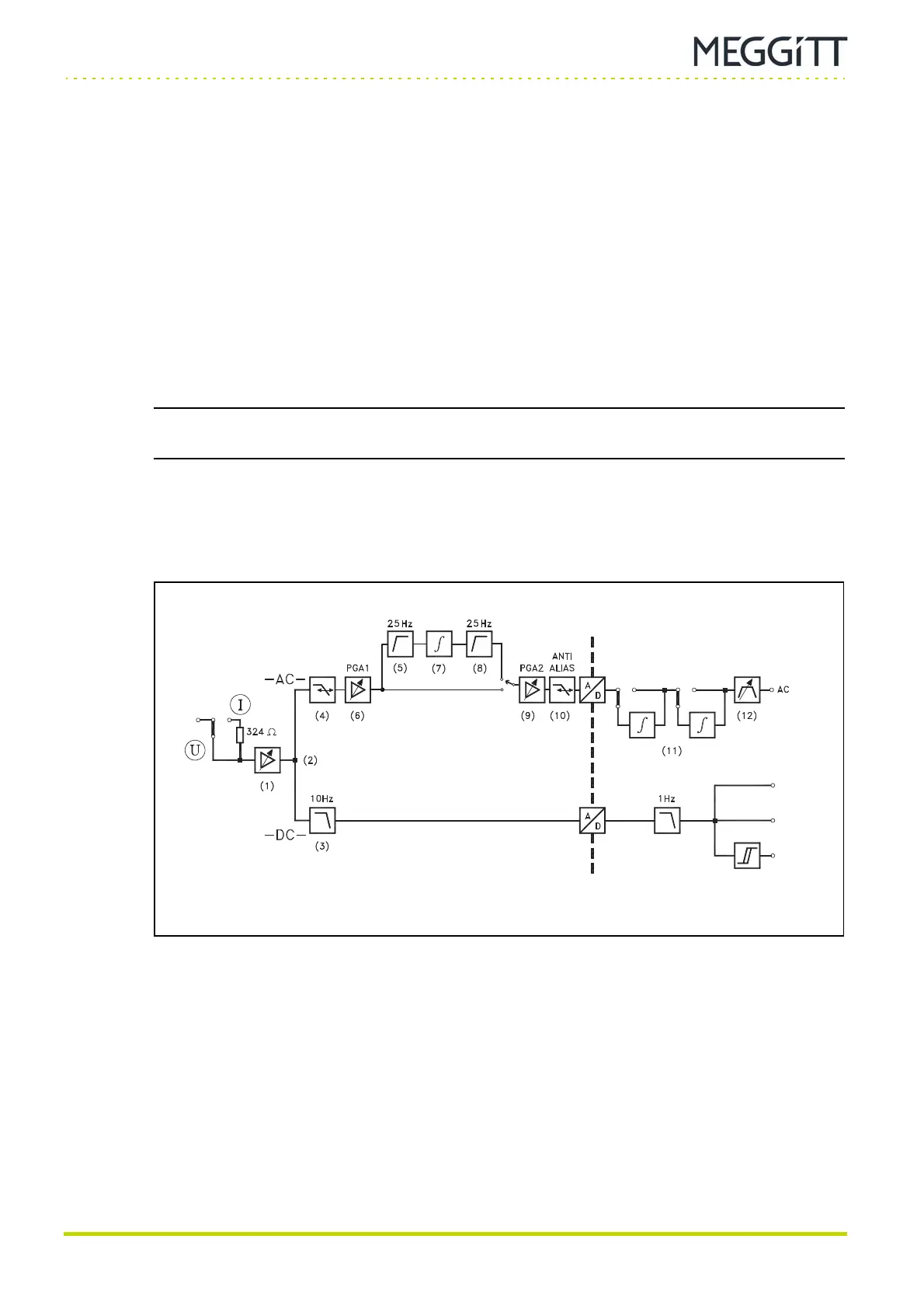
4.4.1.1 Overview of MPC4 signal processing
The signal is processed as shown in the block diagram in Figure 4-4. This applies only to
hardware versions 200-510-100-03x, 200-510-100-1xx and 200-510-100-2xx.
(1) Signal input
If the input signal is current-based, it is read on a 324 Ω resistor to obtain a voltage-based
signal.
The signal then undergoes a first stage of amplification/attenuation (Figure 4-4, Ref. 1).
The DC and AC components of the signal are processed by two separate paths (Figure 4-4,
Ref. 2). These are described below.
(2) Processing of DC component
The DC component is filtered by a low-pass filter (Figure 4-4, Ref. 3) having a cutoff
frequency of 10 Hz. The resulting signal is processed by an analog-to-digital converter (A/D),
which samples this signal every 10 milliseconds.
INTEGRATOR
.
.
Figure 4-4: Signal processing in the MPC4 card
Input
GAP or
”DC value”
“OK value”
“OK fail”
 Loading...
