Document reference MAMPS-HW/E HARDWARE MANUAL
Edition 18 - March 2022 VM600 machinery protection system (MPS)
4-11
Inputs and outputs
MPC4 / IOC4T CARD PAIR
Depending on the sensor and/or signal conditioner type used, 2-wire or 3-wire transmission
lines can be connected to the speed/phase reference inputs of an MPC4 / IOC4T card pair.
NOTE: See 9 Configuration of MPC4 / IOC4T cards for further information on powering
sensors and associated electronic hardware.
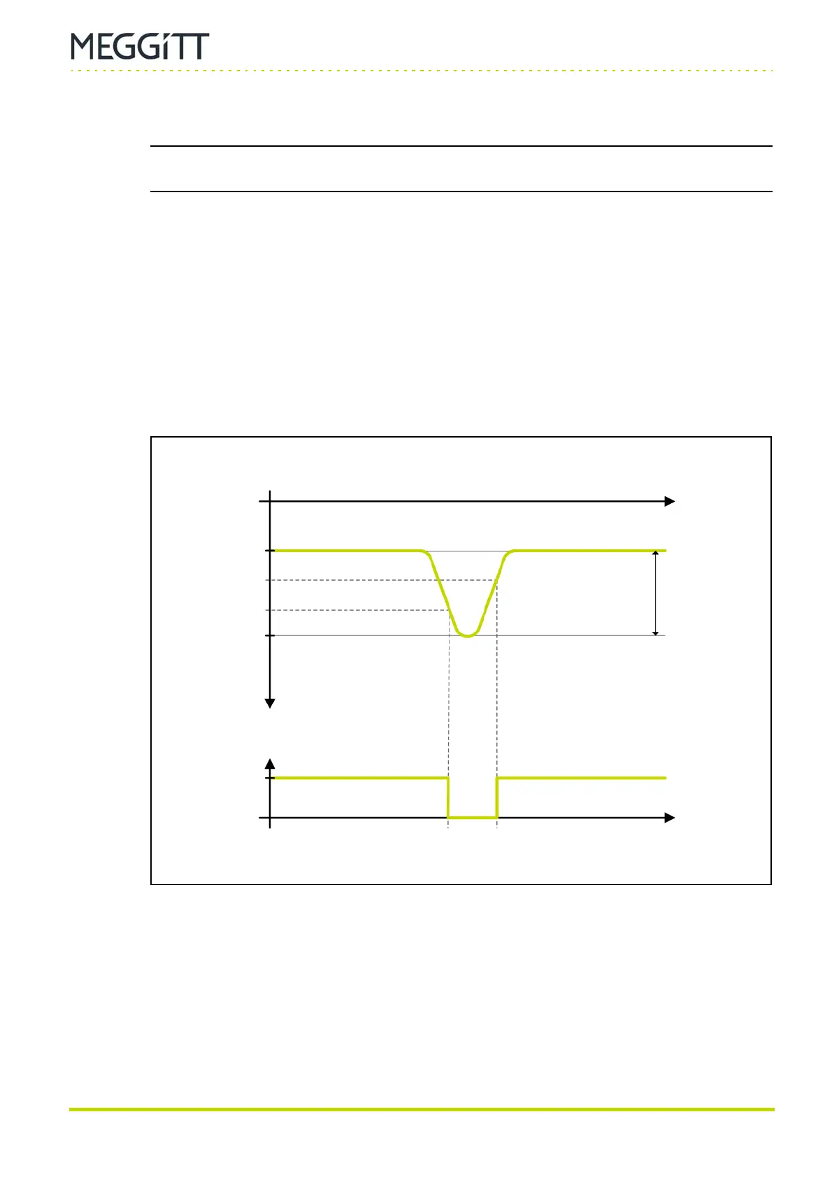
4.4.2.1 Trigger thresholds
As shown in Figure 4-5, the trigger thresholds for a speed/phase reference input signal
depend on the peak to peak amplitude of the input signal.
VT+, the trigger threshold on the falling edge of the input signal, is calculated as follows:
VT+ = V
PEAK−
+⅔(V
PEAK+
−V
PEAK−
)
VT−, the trigger threshold on the rising edge of the input signal, is calculated as follows:
VT− = V
PEAK−
+⅓(V
PEAK+
−V
PEAK−
)
For example, with an input signal that pulses from −7 V to −15 V (that is, 8 V
PEAK-PEAK
):
VT+ = −7 V + ⅔ ( (−15 V) − (−7 V) ) = −7 V + ⅔ (−8 V) = −12.33 V
VT− = −7 V + ⅓ ( (−15 V) − (−7 V) ) = −7 V + ⅓ (−8 V) = −9.66 V
Figure 4-5: Trigger thresholds derived from speed/phase reference inputs
Speed signal
input
Time
Trigger signal
Time
+5 V
V
PEAK+
V
PEAK−
V
T−
V
T+
0V
0V
V
PEAK-PEAK
 Loading...
