HARDWARE MANUAL Document reference MAMPS-HW/E
VM600 machinery protection system (MPS) Edition 18 - March 2022
9-36
Configuring the four DC outputs
CONFIGURATION OF MPC4 / IOC4T CARDS
The DC outputs (DC OUT 1, DC OUT 2, DC OUT 3 and DC OUT 4) share a common
reference/return with the discrete signal interface (DSI) inputs (DB, TM and AR). This
common reference/return is known as RET and is available on Connector J3, Terminal 8
(see 9.1 Definition of screw terminals on the IOC4T card).
NOTE: The common reference/return (RET) signal has a voltage limit of ±2V and a
current limit of 100 mA.
Accordingly, it is recommended to use galvanic separation between the RET on
the IOC4T card and any circuitry connected to the DC outputs if the potential
difference between RET and the external circuitry could be greater than 2 V.
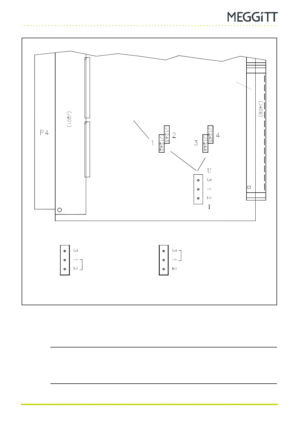
Figure 9-26: Position of jumpers on the IOC4T card related to the DC outputs
(For DC OUT 1)
(Top of card)
(Bottom of card)
Current mode (I)
4to20mA
Voltage mode (U)
0to10V
Connector J3
 Loading...
