EasyManuals Logo

Mercury 75 Service Manual

Mercury 75
574 pages
To Next Page IconTo Next Page
To Previous Page IconTo Previous Page
Page #242 background imageLoading...
Page #242 background image
4-30 - POWERHEAD 90-830234R3 DECEMBER 1997
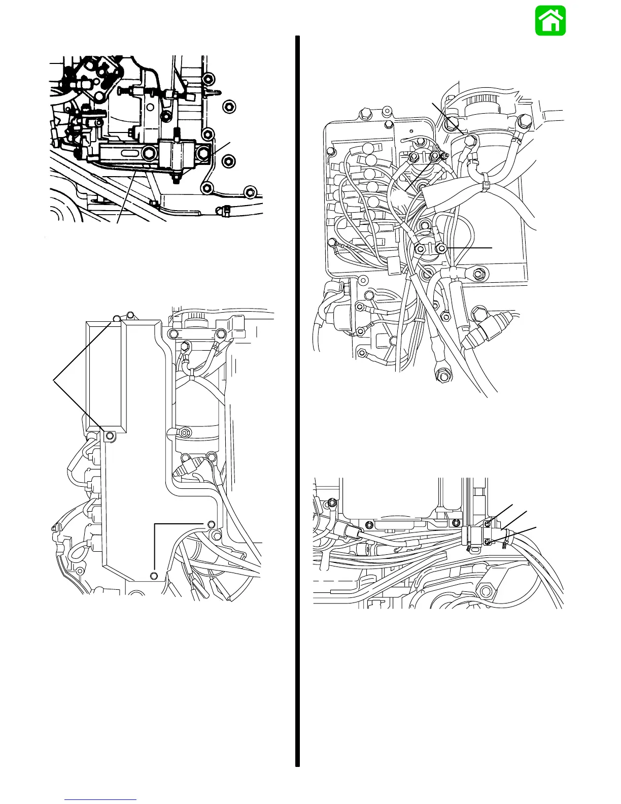
• Remove shift arm linkage at stud.
a
b
19060
a - Shift Arm Linkage
b - Stud
• Remove 4 bolts securing electrical plate cover
and remove cover.
a
a
53958
a - Bolts
• Remove 2 nuts securing GREEN and BLUE trim
harness leads to solenoids. Remove bolt secur-
ing BLACK trim harness lead.
a
b
c
53940
a - GREEN Trim Lead
b - BLUE Trim Lead
c - BLACK Trim Lead
• Remove 2 screws and clamp which secure con-
trol box electrical harness to engine.
a
b
a
20290
a - Screws
b - Clamp

Table of Contents

Other manuals for Mercury 75

Questions and Answers:

Question and Answer IconNeed help?

Do you have a question about the Mercury 75 and is the answer not in the manual?

Mercury 75 Specifications

General IconGeneral
Horsepower75 hp
StartingElectric
Cylinders3
Warranty3 years
Shaft Length20 in. or 25 in.

Related product manuals