90-830234R3 DECEMBER 1997 POWERHEAD - 4-31
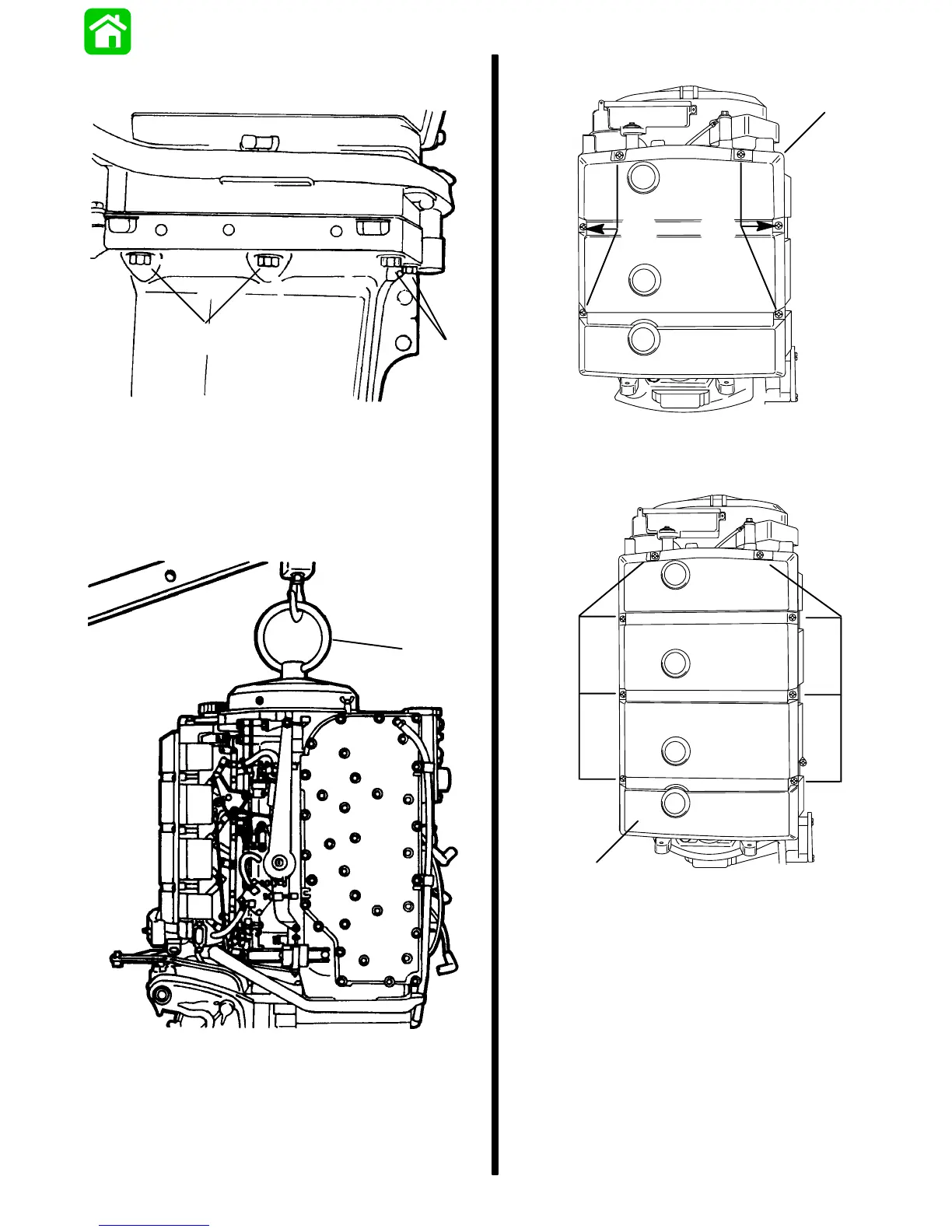
• Remove 8 powerhead to driveshaft housing
mounting nuts and washers (4 each side).
a
a
19070
a - Nuts and Washers (4 Each Side)
• Screw lift eye (91-90455) into flywheel at least 5
full turns.
• Use suitable lifting device to remove powerhead
from driveshaft housing and install on powerhead
stand.
a
25929
a - Lift Eye (91-90455)
• Remove Air Box Cover by removing 6 screws.
a
b
b
3 Cylinder Models
53977
a - Air Box Cover
b - Screws
a
b
b
4 Cylinder Models
53976
a - Air Box Cover
b - Screws
• Remove bolt from lower oil tank support (star-
board side of engine, base).
• Remove bolt from upper oil tank support.
• Remove 2 bolts securing voltage regulator.
• Remove air box by removing nuts/bolts and pull-
ing off of carburetor studs.

 Loading...


