DRIVE SYSTEM AND ENGINE INSTALLATION SECTION - 6
Page 40 / 54 90-899883183 DECEMBER 2007
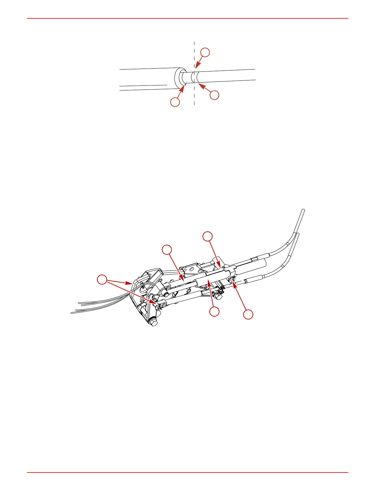
d. Measure distance between marks "a" and "b" and mark position "c" half‑way between
marks "a" and "b."
a
c
b
7815
7. Temporarily install control cable end guide into shift lever and insert anchor pin.
8. Adjust control cable barrel so that hole in barrel centers with vertical centerline of stud. Ensure
that backlash center mark is aligned with edge of control cable end guide.
9. Place remote control and and sterndrive unit in FORWARD gear.
10. Install the remote control shift cable.
11. Place remote control handle in NEUTRAL.
12. Install the shift assist assembly. Ensure that it fits over the clevis pin and barrel stud with no
resistance.
13. Install the fastening hardware. If shift assist assembly attaching points will not align, verify
controller is in neutral. Remove the shift cable and reposition the adjustment barrel as required
to allow the shift assembly to be installed with no effort.
With shift assist assembly
a - Remote control shift cable
b - Shift assist assembly
c - Clevis pin (and cotter pin not shown)
d - Large ID washer
e - Small ID washer and cotter pin

 Loading...
