CHARGING & STARTING SYSTEM
90-855347R1 JANUARY 1999 Page 2B-31
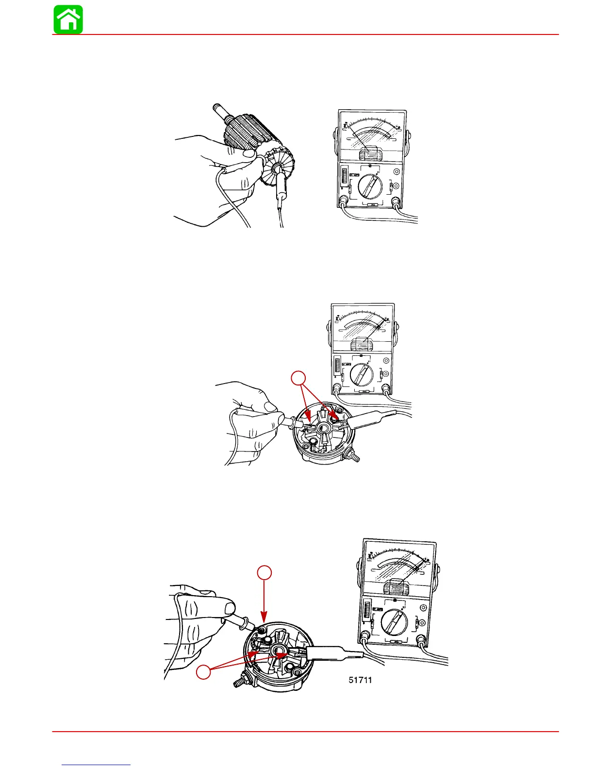
Armature Test for Ground
1. Set ohmmeter to (R x 1 scale). Place one lead of ohmmeter on armature core or shaft
and other lead on commutator.
2. If meter indicates continuity, armature is grounded and must be replaced.
51711
Checking Positive Brushes and Terminal
Set ohmmeter to (R x 1 scale). Connect meter leads between POSITIVE brushes. Meter
must indicate full continuity or zero resistance. If resistance is indicated, inspect lead to
brush and lead to POSITIVE terminal solder connection. If connection cannot be repaired,
brushes must be replaced.
a
51711
a
a-POSITIVE (+) Brushes
Testing Negative Brushes for Ground
Set ohmmeter to (R x1 scale). Place one lead of the ohmmeter on the NEGATIVE brush
and the other lead on the end cap (bare metal). If the meter indicates NO continuity, re-
place the NEGATIVE brush. Repeat this procedure on the other NEGATIVE brush.
a
a
b
a-NEGATIVE (–) Brushes
b-End Cap

 Loading...


