WIRING DIAGRAMS
Page 2D-16 90-855347R1 JANUARY 1999
Multi-Function Gauge
Dip Switch Setting/Testing
NOTE: The multi-function gauge “Dip Switch” must be set on the back of gauge prior to
operation. Turn the ignition switch to the “OFF” position before setting dip switch. The
gauge will reset to selected settings when the ignition is turned “On”.
IMPORTANT: Test the gauge and related wiring BEFORE making final “Dip Switch”
settings and BEFORE securing the gauge to dashboard of boat.
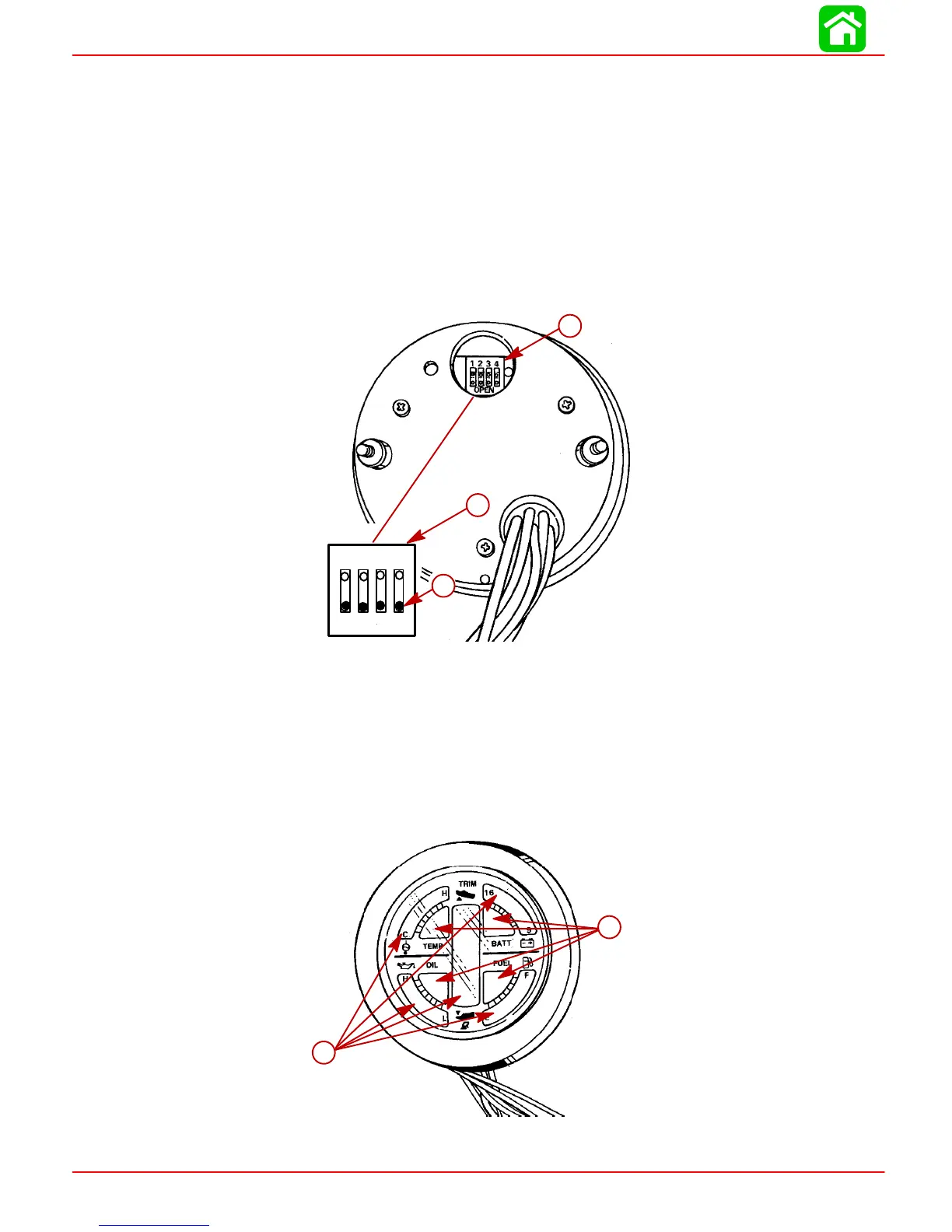
1. With the ignition switch in the “Off” position, set the multi-function gauge “Dip Switch”
in (test) position as shown. (BLACK dot indicates switch position).
a
b
52095
Open
1234
a
a
b
a-“Dip Switch” (shown in test position)
b-Black Dot - Switch in “Open” Position
2. Turn ignition switch to the “Run” position. The multi-function gauge now is in the dis-
play test mode. The gauge Temp, Batt, Oil, and Fuel red warning lights should be alter-
nately flashing “On” and “Off”; the BLACK L.C.D. bar graphs should be cycling. (This
indicates that all gauge functions are operational).
3. Turn ignition switch to the “Off” position. Reset the gauge “Dip Switch” to the correct
operating position for the outboard application.
b
a
a
b
a-Gauge Lights (Red)
b-Gauge L.C.D. Bar Graph (Black)
 Loading...


