DIRECT FUEL INJECTION
90-855347R1 JANUARY 1999 Page 3B-49
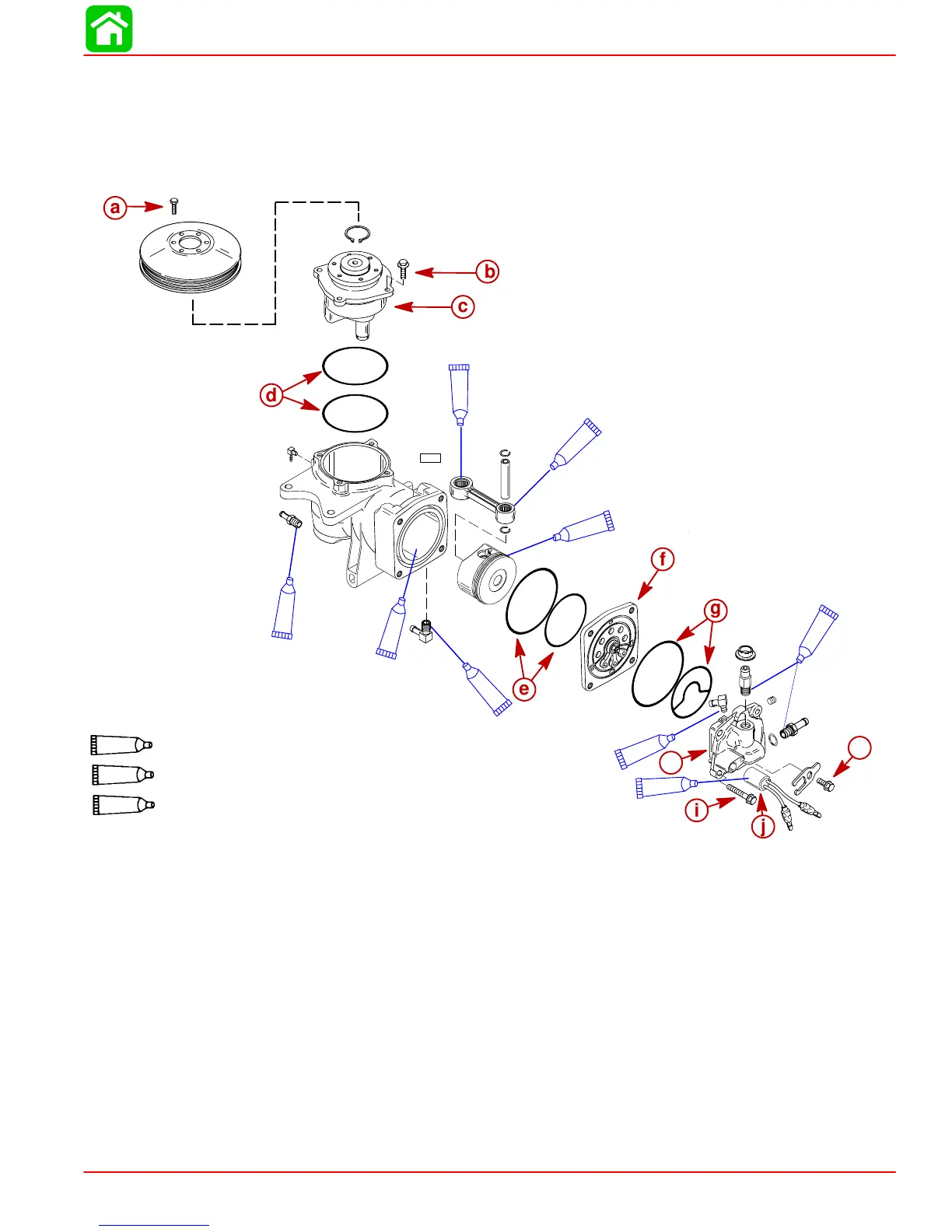
Air Compressor Disassembly/Reassembly
NOTE: If cylinder bore is scored, air compressor must be replaced as an assembly.
NOTE: The piston and rings are not sold separately. They must be replaced as an assem-
bly. The connecting rod and bearings are not sold separately. They must be replaced as
an assembly.
a
b
c
d
e
f
g
i
j
k
9
14
9
14
14
14
9
9
6
h
Dielectric Grease (92-823506--1)
6
Loctite PST Pipe Sealant (92-809822)
9
14
2 Cycle Outboard Oil (92-826666A24)
NOTE: End cap bearing and seal are not sold separately. End cap must be replaced as an assembly
NOTE: Piston Installation – use a metal hose clamp for piston ring compressor. Stagger piston ring openings.
a-Bolt [Torque to 100 lb. in. (11.5 Nm)]
b-Bolt (4 each) [Torque to 100 lb. in. (11.5 Nm)]
c-End Cap Assembly (Inspect bearing for
roughness)
d-O-rings (Inspect for cuts or abrasions)
e-O-rings (Inspect for cuts or abrasions)
f-Reed Plate (Inspect for broken or chipped
reeds/stops) Maximum Reed Stand-Open –
0.010 in. (0.254 mm)
g-O-rings (Inspect for cuts or abrasions)
h-Cylinder Head
i-Bolt [Torque to 20 lb. ft. (27 Nm)]
j-Temperature Sensor
k-Bolt [Torque to 20 lb. ft. (27 Nm)]

 Loading...


