CHARGING & STARTING SYSTEM
Page 2B-20 90-855347R1 JANUARY 1999
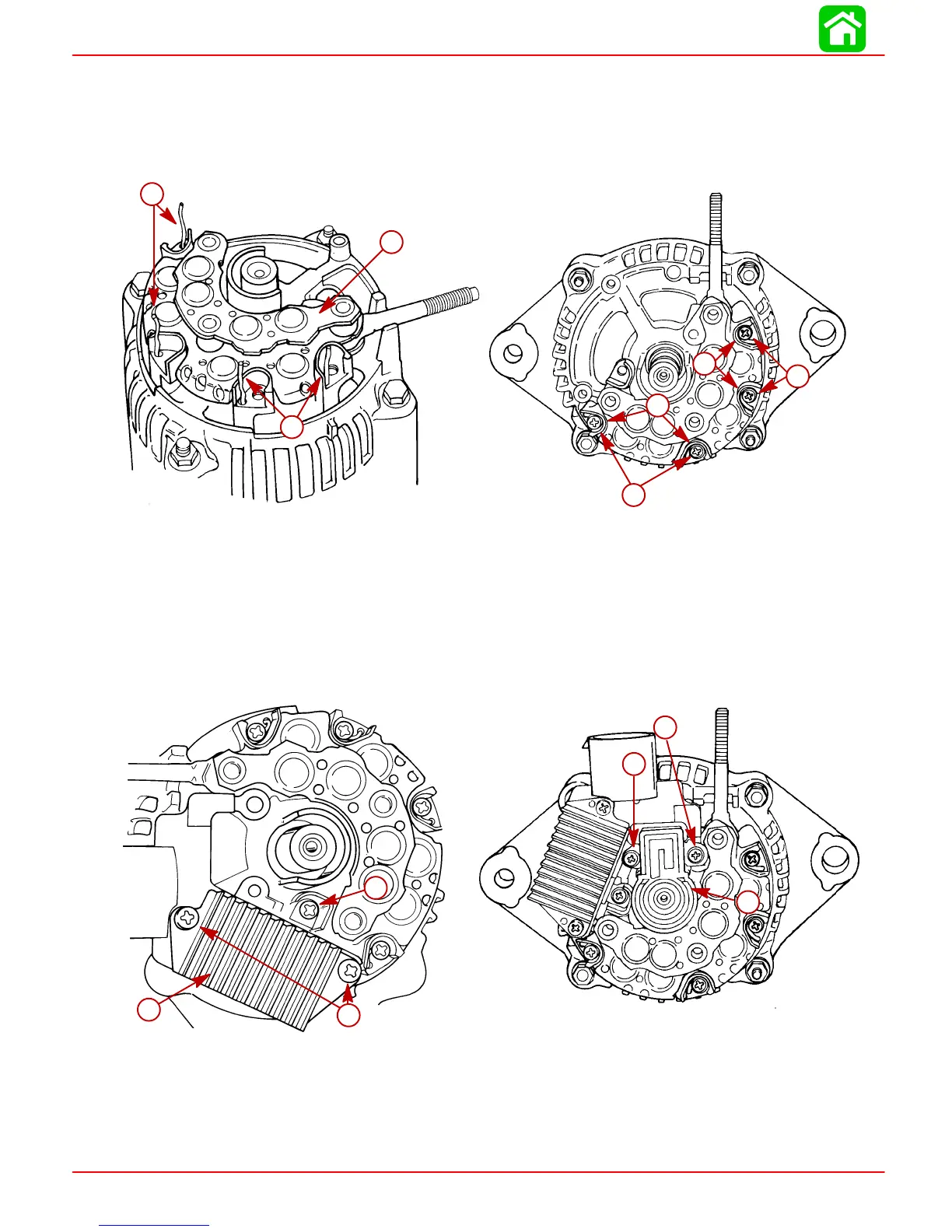
Reassembly
1. Position rectifier assembly over stator leads.
2. Form stator leads in a clockwise loop and secure leads to rectifier with 4 screws.
Torque screws to 17 lb-in (1.9 Nm).
51684
b
b
a
a
c
c
d
d
51683
b
a
b
a
b
b
a-Rectifier Assembly
b-Stator Leads
c-Stator Leads
d-Screws [Torque to 17 lb-in (1.9 Nm)]
3. Secure regulator to alternator with 2 screws [1 in. (25.4 mm) long]; 1 screw [0.25 in.
(6.4 mm) long] and lockwashers. DO NOT tighten screws at this time.
4. Secure brush assembly with 2 screws – [0.25 in. (6.4 mm) long] and [0.312 in. (8.0
mm) long].
51680
b
c
a
d
e
f
51684
c
a
a
b
c
a-Regulator
b-Screws [1 in. (25.4 mm)]
c-Screw [0.25 in. (6.4 mm)]
d-Brush Assembly
e-Screw [0.25 in. (6.4 mm)]
f-Screw [0.312 in. (8.0 mm)]