CHARGING & STARTING SYSTEM
Page 2B-14 90-855347R1 JANUARY 1999
Voltage Output
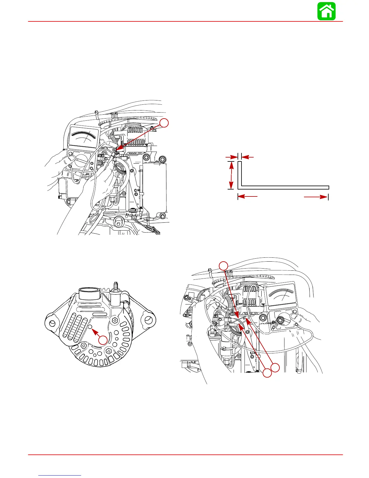
1. Using a 0-20 volt DC voltmeter, connect POSITIVE (+) lead of voltmeter to TERMINAL
B of alternator and NEGATIVE (–) lead of voltmeter to engine ground.
2. Start engine and allow to warm up. Increase engine RPM from idle to 2000. Normal
voltage output should be 13.5 – 15.1 volts. If voltage reading is greater than normal,
replace voltage regulator.
3. If voltage reading is less than normal, fabricate a tool from a piece of stiff wire to the
following specifications:
8 in. (203 mm)
13/16 in. (20.6 mm)
0.060 in. (1.52 mm)
VOLTS
DC AMPS
OHMS
0
2
4
6
8
10
DCV
ACV
DVA
0
0
5
10
20
10
30
15
40
20
0
5
10
15
20
30
40
60
100
200
56113
a
a
a-Terminal B
4. Insert bent end of tool through end cover and ground TERMINAL F.
56115
VOLTS
DC AMPS
OHMS
0
2
4
6
8
10
DCV
ACV
DVA
0
0
5
10
20
10
30
15
40
20
0
5
10
15
20
30
40
60
100
200
b
a
c
51683
a
a
b
c
a
a-Terminal F
b-Tool
c-Jumper Wire to Engine Ground (Attach to end of Tool)
5. With TERMINAL F grounded, voltage should rise to within the normal range (13.5 –
15.1). If voltage rises, replace the regulator.
6. If the voltage DOES NOT rise to within the normal range with TERMINAL F grounded,
perform “CURRENT OUTPUT” test.

 Loading...


