POWER TRIM
90-855347R1 JANUARY 1999 Page 5B-15
Electrical System Troubleshooting
General Checks
Before troubleshooting the Power Trim electrical system, check the following:
1. Check for disconnected wires.
2. Make certain all connections are tight and corrosion free.
3. Check that plug-in connectors are fully engaged.
4. Make certain battery is fully charged.
Refer to the preceding four wiring diagrams for connection points when troubleshooting
the electrical systems (Connection points are specified by number.)
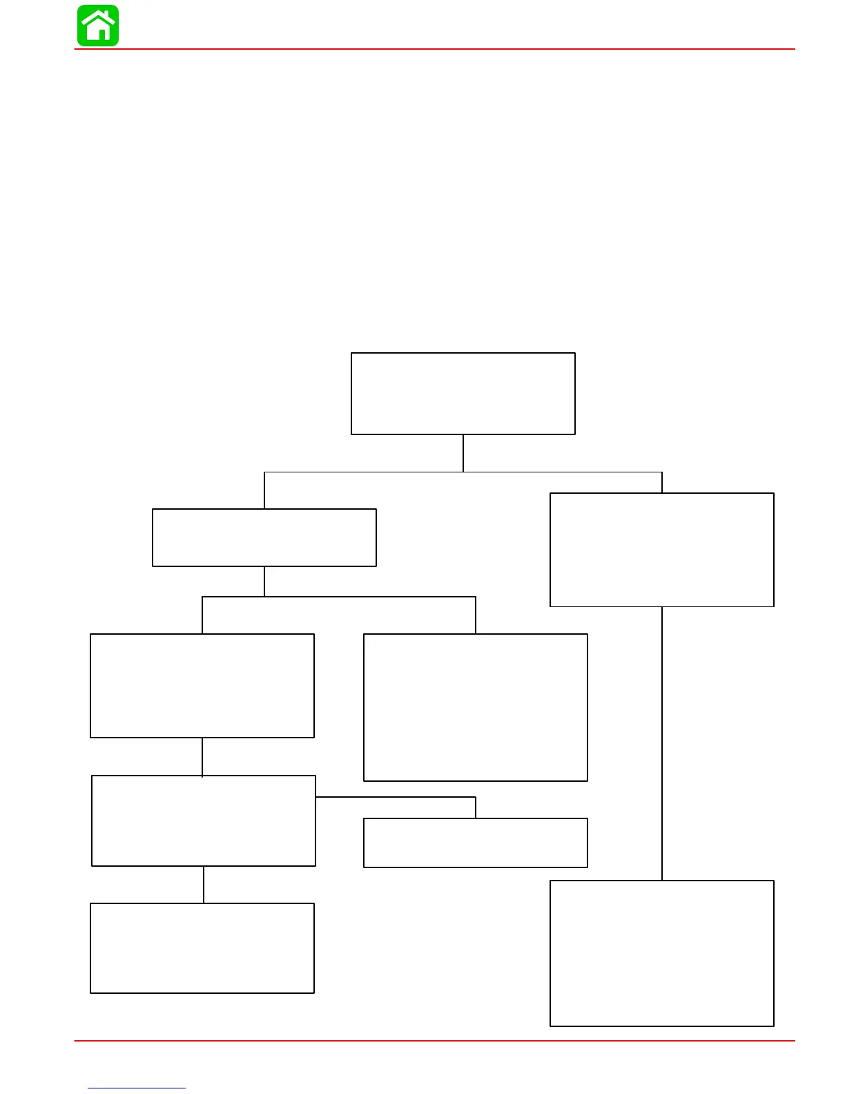
Troubleshooting the “Down Circuit”
Battery Voltage Indicated:
Battery Voltage Indicated:
Relay good:
No Voltage Indicated:
No Voltage Indicated:
No Voltage Indicated:
No Voltage Indicated:
Connect Voltmeter red lead to
Point 5. If battery voltage is indi-
cated, trim switch is faulty. If no
battery voltage, check for loose
or corroded connection at Point
5 or open circuit in wire supply-
ing current to Point 5.
Relay Switch is defective.
There is an open circuit be-
tween Point 3 and positive (+)
battery terminal.
•Connect Voltmeter red lead to
Point 2.
Connect Voltmeter red lead to
Point 3.
Connect Voltmeter red lead to
Point 4 and black lead to ground.
Depress “Down” trim button. If
battery voltage is indicated, wire
is open between Points 4 and 1.
Connect Voltmeter red lead to
Point 1 and black lead to ground.
Depress the “Down” trim button.
•Depress “Down” trim button.
•Pump motor wiring is defec-
tive.
•Pump motor is defective.
•Check for loose or corroded
connections.
•Check wires for open.
Battery Voltage Indicated:
•Test UP relay.
Refer to page 5B-13 for relay
test procedure.