POWER TRIM
90-855347R1 JANUARY 1999 Page 5B-47
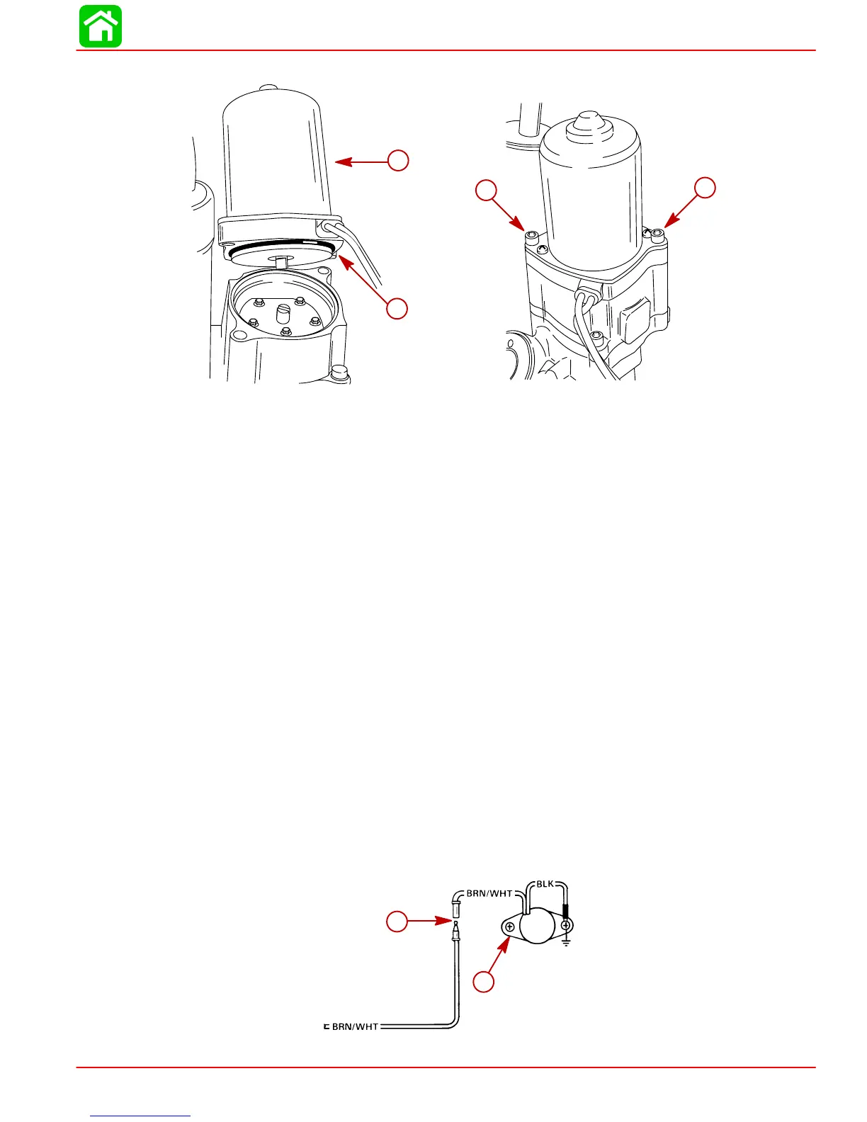
NOTE: Verify motor and drive shaft are aligned.
53782
53777
a
b
c
c
a-Motor
b-O-ring
c-Screw (2) Tighten securely.
4. Complete reassembly of Power Trim System as outlined in “Installation” on page
5B-21.
Priming Power Trim System
1. Fill system with Quicksilver Power Trim and Steering Fluid or Automatic Transmission
Fluid (ATF) Type F,FA, Dexron II or Dexron III. Refer to “Fill, Check, and Purge” on
page 5B-10.
IMPORTANT: Run Trim System in short “jogs” until pump motor primes and trim
system moves. If trim motor is run without priming pump, drive shaft failure could
result.
Trim Sender Test
1. Check trim sender black lead for proper ground.
2. Trim outboard to full “DOWN” position.
3. Place ignition switch to “ON” position.
4. Disconnect BRN/WHT trim sender wire from trim sender harness.
5. Connect Ohmmeter (Rx1 scale) leads between outboard ground and Point 1 (trim
sender end).
6. Depress “UP” button. Ohmmeter needle should move as the outboard is trimmed up.
If needle does not move, trim sender is defective.
a
1
22908
a-Trim sender