EasyManuals Logo

Mercury Optimax 115 User Manual

Mercury Optimax 115
522 pages
To Next Page IconTo Next Page
To Previous Page IconTo Previous Page
Page #30 background imageLoading...
Page #30 background image
GENERAL INFORMATION
90-855347R1 JANUARY 1999 Page 1C-9
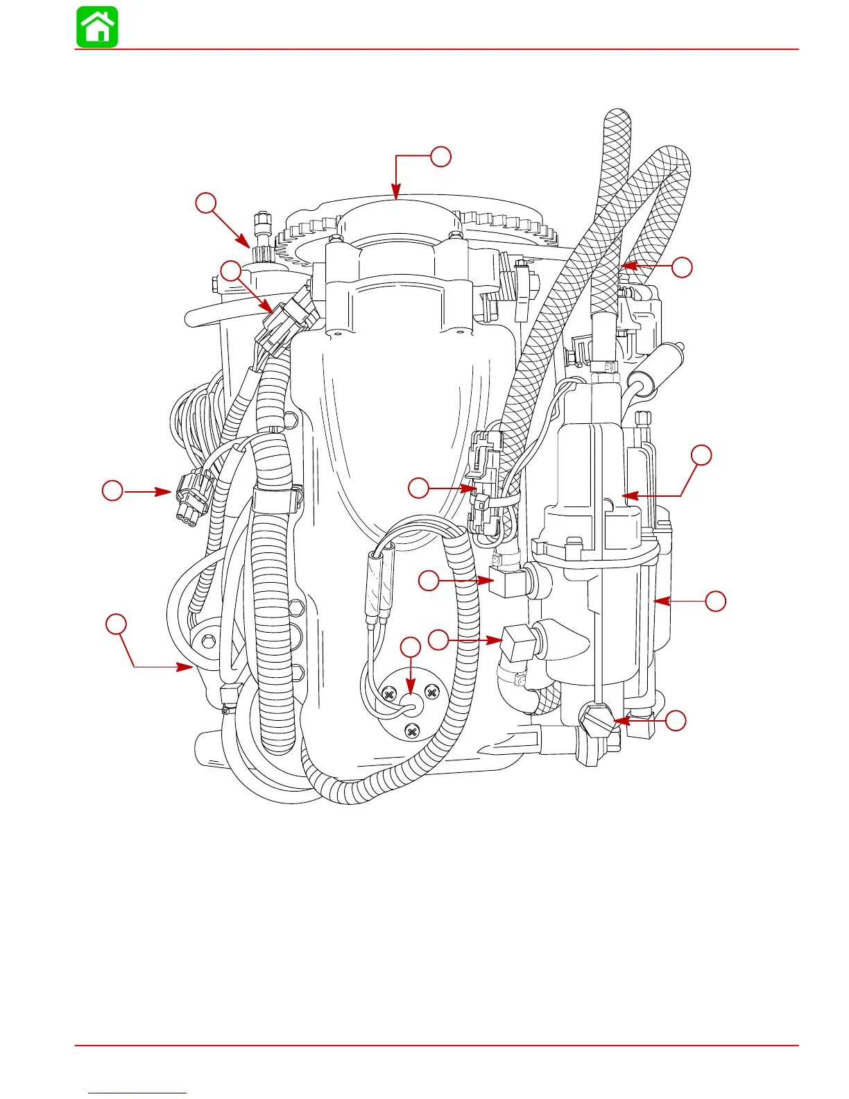
Model 135/150 DFI Powerhead Front View
57314
10
12
11
13
3
2
1
5
6
7
4
8
9
1-High Pressure Electric Fuel Pump (Inside Vapor Separator)
2-Vapor Separator
3-Vapor Separator Drain Plug
4-Air Temperature Sensor
5-Fuel Hose Outlet from Low Pressure Electric Fuel Pump
6-Fuel Return Hose from Fuel Cooler
7-Electric Fuel Pump Harness Connection
8-Electric Oil Pump (Hidden)
9-Digital Diagnostic Terminal Harness Connection
10 - Crank Position Sensor Harness Connection
11 - Starter Motor
12 - Throttle Plate Assembly
13 - Fuel Hose Out to Fuel Rails (High Pressure)

Table of Contents

Other manuals for Mercury Optimax 115

Questions and Answers:

Question and Answer IconNeed help?

Do you have a question about the Mercury Optimax 115 and is the answer not in the manual?

Mercury Optimax 115 Specifications

General IconGeneral
Fuel Induction System2-stage Direct Fuel Injection (DFI)
Alternator Amp60 amp / 756 watt
SteeringRemote
Cylinders3
StartingElectric
Displacement1.5 L
Bore x Stroke89 x 76 mm
Shaft Length20" (508 mm)
Horsepower115 HP

Related product manuals