EasyManuals Logo

Mercury Optimax 115 User Manual

Mercury Optimax 115
522 pages
To Next Page IconTo Next Page
To Previous Page IconTo Previous Page
Page #95 background imageLoading...
Page #95 background image
CHARGING & STARTING SYSTEM
90-855347R1 JANUARY 1999 Page 2B-21
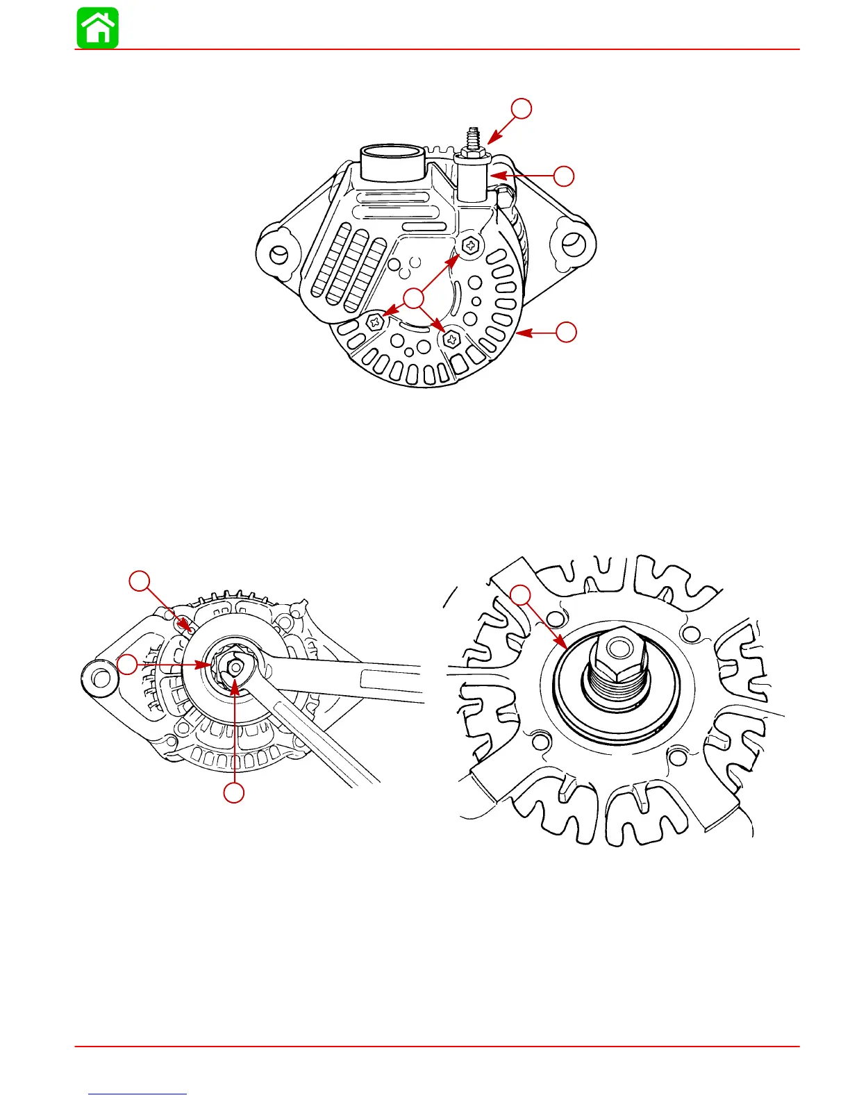
5. Install end cover. Secure cover with 3 screws. Torque screws to 23 lb-in. (2.5 Nm).
Install terminal insulator. Torque nut to 36 lb-in (4 Nm).
51683
d
c
a
b
a
b
c
d
a-Cover
b-Screw [Torque to 23 lb-in (2.5 Nm)]
c-Terminal Insulator
d-Nut [Torque to 36 lb-in. (4 Nm)]
Pulley
1. While holding rotor shaft, remove pulley nut.
2. Before reinstalling pulley, verify spacer is installed on rotor shaft.
51683
a
d
51679
a
c
b
a
b
c
a-Pulley
b-Rotor Shaft
c-Nut
d-Spacer
3. Torque pulley nut to 50 lb-ft (68 Nm).

Table of Contents

Other manuals for Mercury Optimax 115

Questions and Answers:

Question and Answer IconNeed help?

Do you have a question about the Mercury Optimax 115 and is the answer not in the manual?

Mercury Optimax 115 Specifications

General IconGeneral
Fuel Induction System2-stage Direct Fuel Injection (DFI)
Alternator Amp60 amp / 756 watt
SteeringRemote
Cylinders3
StartingElectric
Displacement1.5 L
Bore x Stroke89 x 76 mm
Shaft Length20" (508 mm)
Horsepower115 HP

Related product manuals