CHARGING & STARTING SYSTEM
90-855347R1 JANUARY 1999 Page 2B-15
Current Output
1. With engine shut off, install ammeter (capable of reading 60+ amperes) in series be-
tween TERMINAL B on alternator and POSITIVE (+) terminal of battery.
2. Start engine and allow to warm up. Advance RPM to 2000.
3. Insert tool, previously fabricated for VOLTAGE OUTPUT, through end cover and
ground TERMINAL F.
56116
b
e
a
d
c
a-Terminal F
b-Tool
c-Jumper Wire to Engine Ground
d-Terminal B
e-Ammeter
4. Normal output is 60 amperes @ 2000 RPM. If output is normal, replace regulator. If
output is low, a disassembly of the alternator is necessary to inspect and test individ-
ual components.
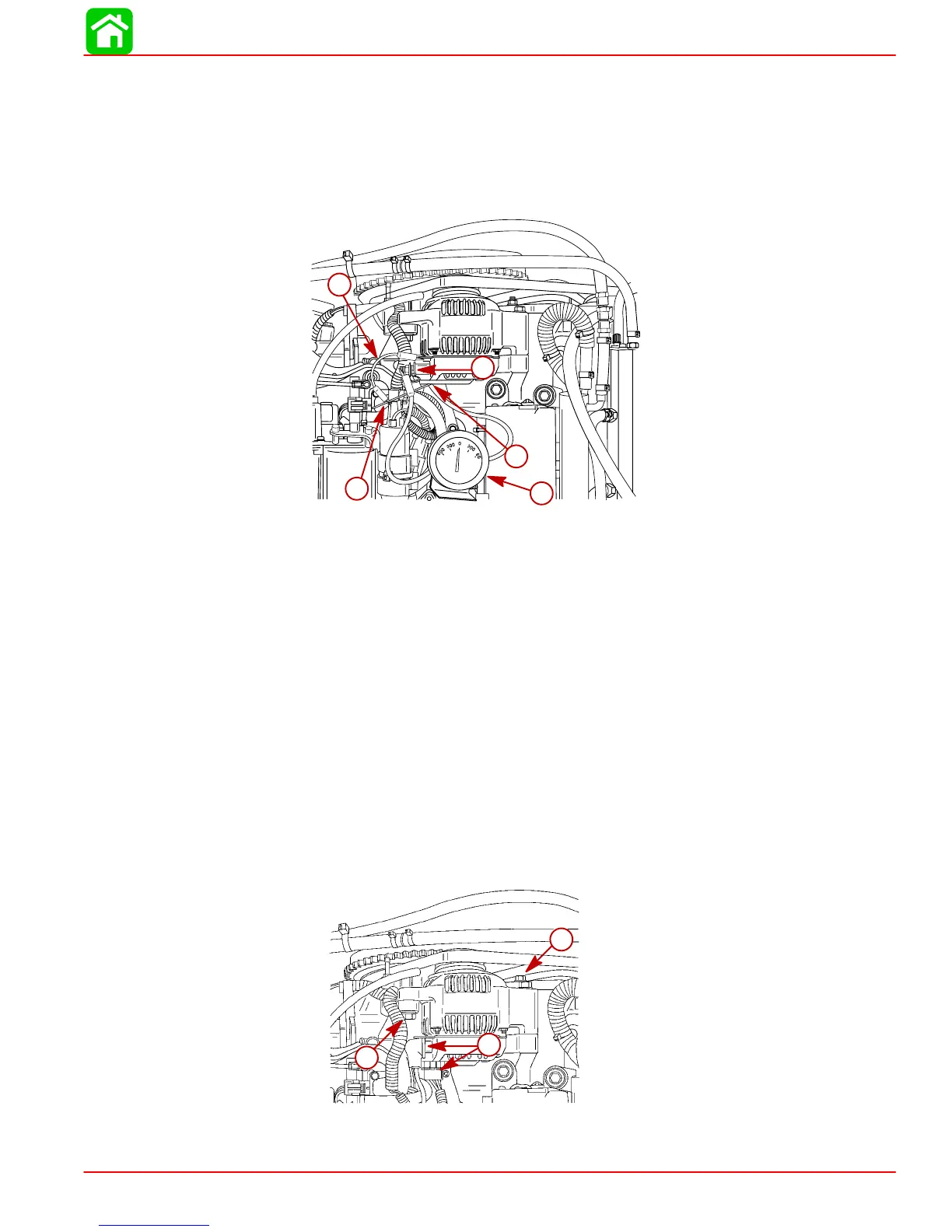
Repair
Removal
1. Remove top cowling.
2. Disconnect battery cables from battery.
3. Disconnect wiring harness from alternator.
4. Remove pivot bolt and tension bolt.
a
a
b
56117
a
b
a
a-Attaching Bolt
b-Harnesses