GENERAL INFORMATION
90-855347R1 JANUARY 1999 Page 1C-13
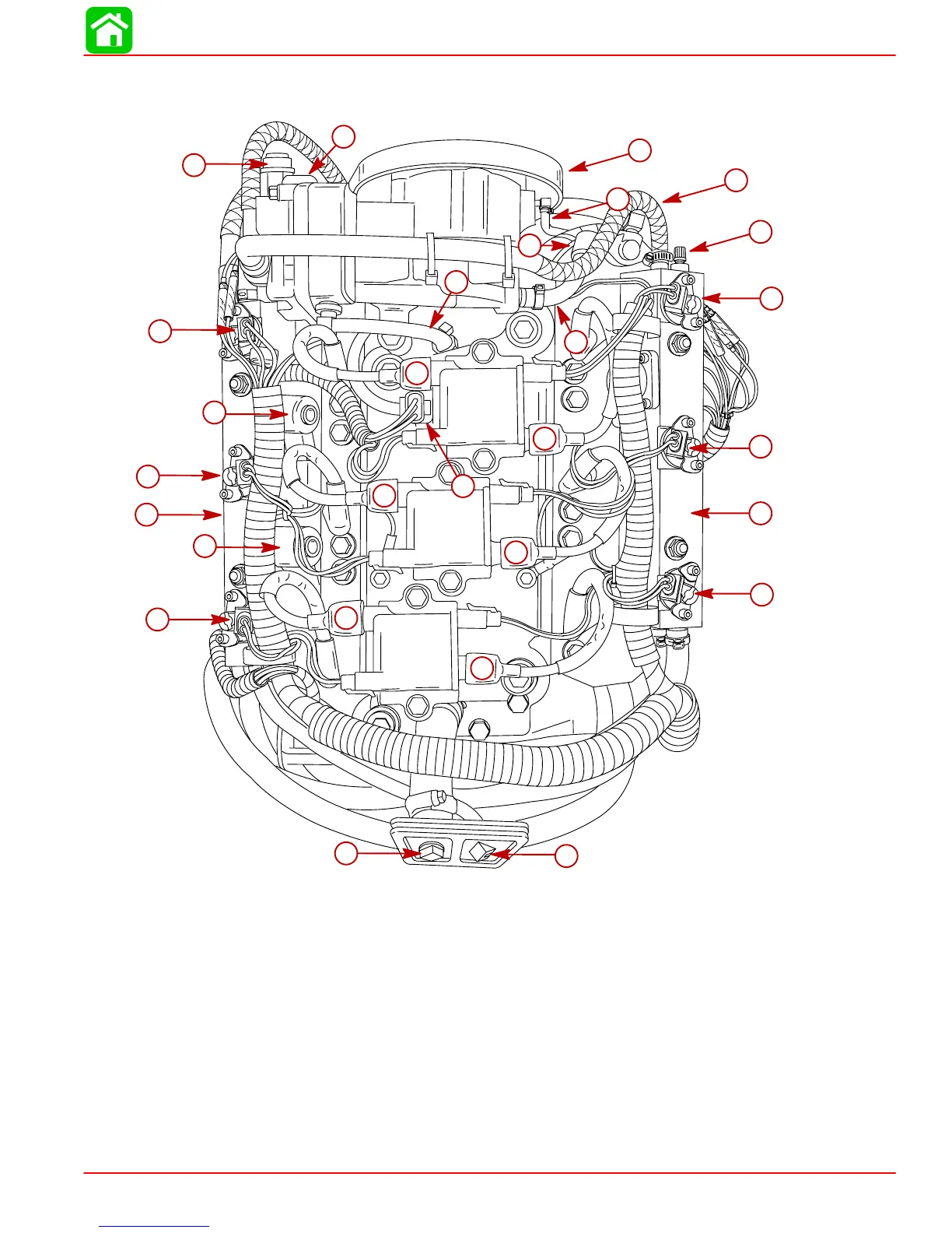
Model 135/150 DFI Powerhead Aft View
57315
17
25
1
3
4
5
6
7
8
9
10
11
12
2
13
14
15
16
18
19
20
21
22
23
24
26
27
28
1-Air Compressor Restrictor/Air Inlet
2-Water Out (tell-tale) from Air Compressor
3-Air Compressor Oil Inlet from Oil Pump
4-Air Compressor
5-Air Pressure Out (80 psi)
6-Fuel Pressure Test Valve
7-Check Valve
8-Excess Oil Return from Air Compressor
9-#1 Fuel Injector
10 - Starboard Fuel Rail
11 - #3 Fuel Injector
12 - #5 Fuel Injector
13 - Tell-Tale Outlet
14 - Flush Plug
15 - #5 Ignition Coil
16 - #3 Ignition Coil
17 - #1 Ignition Coil
18 - Water Inlet to Air Compressor
19 - #2 Ignition Coil
20 - MAP Sensor
21 - #4 Ignition Coil
22 - #6 Ignition Coil
23 - #6 Fuel Injector
24 - Air Regulator
25 - Port Fuel Rail
26 - #4 Fuel Injector
27 - Fuel Regulator
28 - #2 Fuel Injector