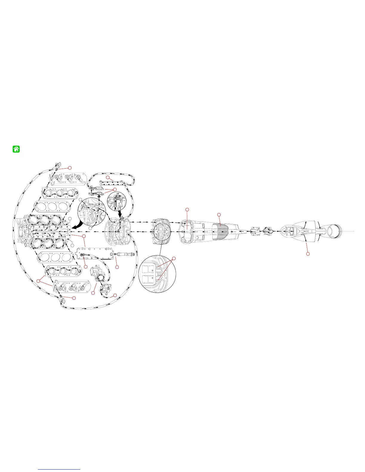
Cylinder Block and Adaptor Plate
Drive Shaft Housing
Lower Unit and Water Pump
A
BOTTOM VIEW
B
B
A
57339
1
2
3
3
4
5
6
7
8
9
10
11
1 - Air Compressor
2 - Cylinder Head Cover – Removed from head for illustra-
tion, normally part of head casting
3 - Thermostats (2) 143° F (61.6° C) – If stuck closed, engine
will overheat at idle.
4 - Strainer Screen for air compressor water supply – If re-
stricted, compressor will overheat and tell-tale will be weak.
5 - Exhaust Divider Plate – Separated for illustration
6 - Poppet Valve – Controls water flow at high RPM.
Note: If poppet valve is stuck open at low RPM, the engine
will not reach proper operating temperature (run cold) and
will run rough at idle.
7 - Fuel Cooler – If internal leak occurs, fuel will be forced into
cooling system.
8 - Water Outlet from Air Compressor – Connects to tell-tale
outlet on bottom cowl.
9 - Water Dump Holes Exhaust Cooling (2 each) 1/8 in. (3.175 mm)
– If holes are plugged, tuner pipe will melt and bearing carrier
prop shaft seals will be damaged.
10- Water Tube
11- Wall of Water – If water level height is insufficient, water
pump may draw in air resulting in an overheated engine.
12- Check Valve for powerhead flush.
13- Excess water from wall of water around exhaust bucket exits
around anodes
.
12
13
90-855347R1 JANUARY 1999
Page 4B-5
1998/1999 Water Flow Diagram