TIMING, SYNCHRONIZING & ADJUSTING
Page 2C-4 90-855347R1 JANUARY 1999
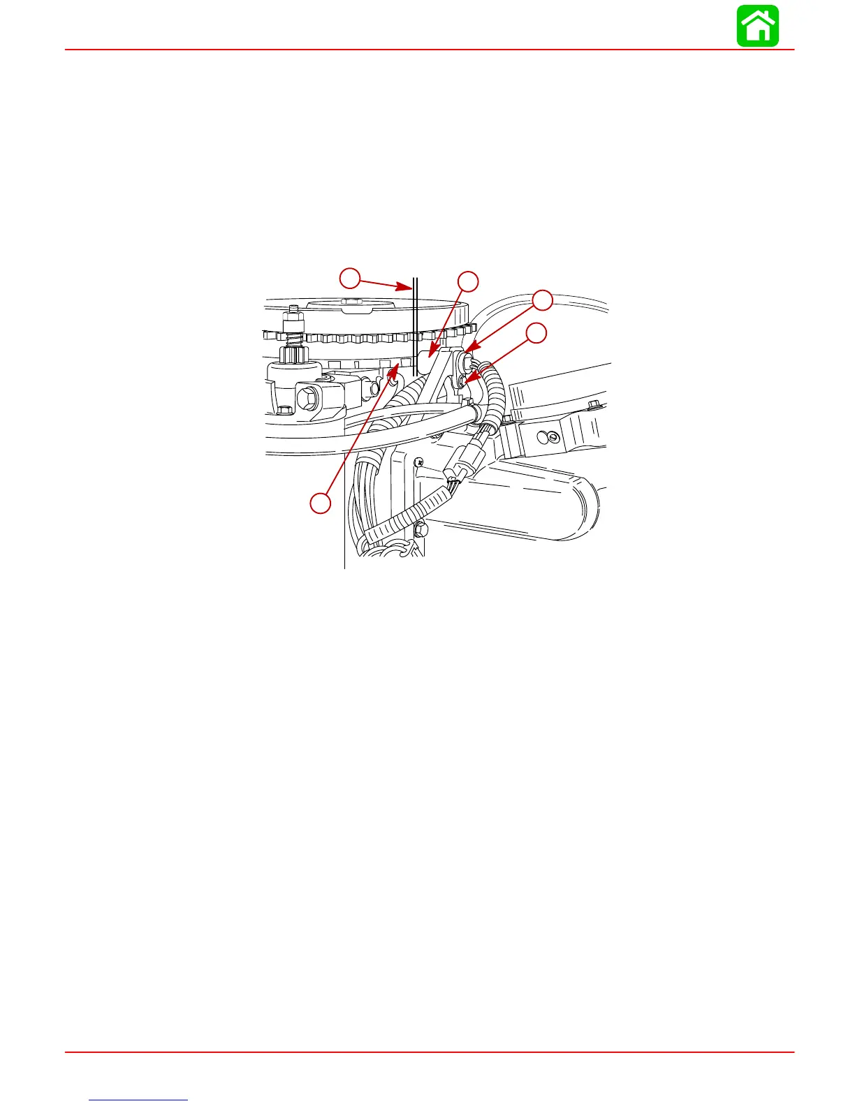
Crank Position Sensor
NOTE: Crank Position Sensor is normally not adjustable, but shims are available if sensor
is found to be to close to flywheel.
1. Remove flywheel cover.
2. Using a feeler gauge, measure the air gap between the crank position sensor and a
tooth on the flywheel. Gap should be 0.025 in. - 0.040 in. (0.635 mm - 1.02 mm).
IMPORTANT: Crank Position Sensor must be perpendicular to flywheel tooth.
3. Reinstall flywheel cover.
d
c
56069
a
c
d
b
e
a-Air Gap [0.025 in - 0.040 in.(0.635 mm - 1.02 mm)]
b-Crank Position Sensor
c-Flywheel Tooth
d-Bracket Screw (Drive Tight)
e-0.010 in. (0.254 mm) or 0.020 in. (0.508 mm) Shim if required – refer to parts
manual

 Loading...


