CHARGING & STARTING SYSTEM
90-855347R1 JANUARY 1999 Page 2B-13
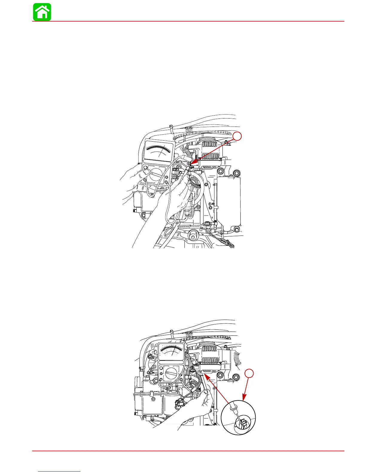
Alternator System Circuitry Test
Using a 0-20 volt DC voltmeter, perform the following tests:
Output Circuit
1. Connect POSITIVE (+) voltmeter lead to alternator terminal B (output terminal). Con-
nect NEGATIVE (–) lead to case ground on alternator.
2. Shake alternator wiring harness. Meter should indicate battery voltage and should not
vary. If proper reading is not obtained, check for loose or dirty connections or dam-
aged wiring.
VOLTS
DC AMPS
OHMS
0
2
4
6
8
10
DCV
ACV
DVA
0
0
5
10
20
10
30
15
40
20
0
5
10
15
20
30
40
60
100
200
56113
a
a
a-Terminal B
Sensing Circuit
1. Unplug RED and PURPLE lead connector from alternator.
2. Connect POSITIVE (+) voltmeter lead to RED lead and NEGATIVE (–) voltmeter lead
to ground.
3. Voltmeter should indicate battery voltage. If correct voltage is not present, check
sensing circuit (RED lead) for loose or dirty connections or damaged wiring.
56114
a
a
a-Sense Lead (RED)