POWER TRIM
Page 5B-46 90-855347R1 JANUARY 1999
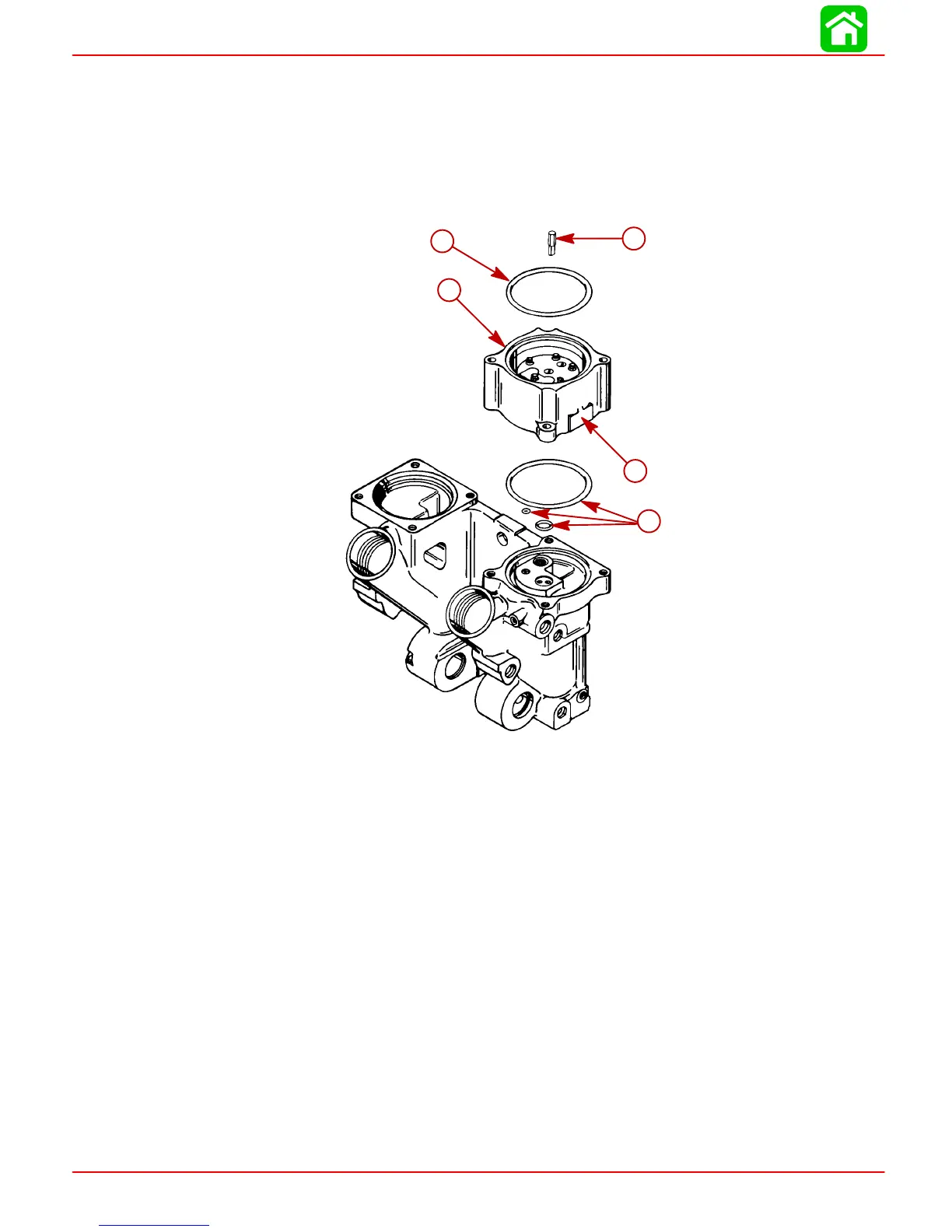
Reassembly - Motor and Pump
NOTE: Drive shaft is a loose part and may fall out of position.
1. Install pump onto power trim manifold. Insure O-rings are in proper locations. Secure
with two (2) screws. Torque screws to 80 lb. in. (9 N·m).
IMPORTANT: Install pump with location flat facing towards starboard transom
bracket.
51433
a
b
c
d
c
a-Pump (Flat Towards Starboard Transom Bracket)
b-Flat - Faces Starboard Transom Bracket)
c-O-rings (4)
d-Drive Shaft (Install in Center Hole in Pump)
2. Fill pump with Quicksilver Power Trim and Steering Fluid prior to installing motor.
3. Install motor, secure with two (2) screws. Route wiring; refer to Wiring Diagrams in this
service manual.

 Loading...


